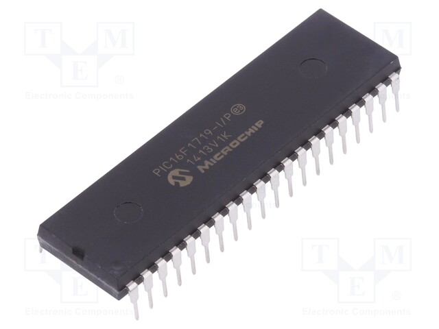
Decrypt Secured MCU PIC16F1719 Flash Binary
Decrypt Secured MCU PIC16F1719 Flash Binary from its locked memory, the embedded firmware can be extracted from microcontroller pic16f1719, tamper resistance system of pic16f1719 microchip controller can be reversed;
The ADCON0 register, shown in Register 17-1, controls the operation of the A/D module. The ADCON1 register, shown in Register 17-2, configures the functions of the port pins. The ADCON2 register, shown in Register 17-3, configures the A/D clock source, programmed acquisition time and justification.
If the A/D FRC clock source is selected, a delay of one TCY (instruction cycle) is added before the A/D clock starts. This allows the SLEEP instruction to be executed before starting a conversion.
If the A/D FRC clock source is selected, a delay of one TCY (instruction cycle) is added before the A/D clock starts to unlock pic16f1613t mcu flash firmware. This allows the SLEEP instruction to be executed before starting a conversion.
A device Reset forces all registers to their Reset state. This forces the A/D module to be turned off and any conversion in progress is aborted. Each port pin associated with the A/D converter can be configured as an analog input, or as a digital I/O.
The ADRESH and ADRESL registers contain the result of the A/D conversion. When the A/D conversion is complete when extracting pic16f1509t microcontroller flash memory firmware, the result is loaded into the ADRESH/ADRESL registers, the GO/DONE bit (ADCON0 register) is cleared and A/D Interrupt Flag bit, ADIF, is set. The block diagram of the A/D module is shown in below Figure.