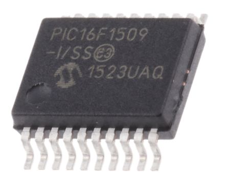
Extract Microcontroller PIC16F1509T Flash Memory Firmware
Extract Microcontroller PIC16F1509T Flash Memory Firmware needs to reverse engineering pic16f1509t mcu security fuse bit, then read embedded program out from pic16f1509t microprocessor;
The operation of the Synchronous Master and Slave modes is identical, except in the case of Sleep, or any Idle mode and bit SREN, which is a “don’t care” in Slave mode. If receive is enabled by setting the CREN bit prior to entering Sleep or any Idle mode, then a word may be received while in this low-power mode.
Once the word is received, the RSR register will transfer the data to the RCREG register; if the RCIE enable bit is set, the inter- rupt generated will wake the chip from low-power mode by cloning pic16f1574 microcontroller flash heximal file. If the global interrupt is enabled, the program will branch to the interrupt vector.
To set up a Synchronous Slave Reception:
- Enable the synchronous master serial port by setting bits SYNC and SPEN and clearing bit CSRC.
- If interrupts are desired, set enable bit RCIE.
- If 9-bit reception is desired, set bit RX9.
- To enable reception, set enable bit CREN.
- Flag bit, RCIF, will be set when reception is complete. An interrupt will be generated if enable bit, RCIE, was set.
- Read the RCSTA register to get the ninth bit (if enabled) and determine if any error occurred during reception.
- Read the 8-bit received data by reading the RCREG register.
- If any error occurred, clear the error by clearing bit CREN.
- If using interrupts, ensure that the GIE and PEIE bits in the INTCON register (INTCON<7:6>) are set.