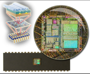
Restore DSP CPU TMS320F28030PAGT Source Code
The five possible reset signals are generated as follows which can effectively affect the process of Restore DSP CPU TMS320F28030PAGT Source Code:
Watchdog timer reset. A watchdog-timer-generated reset occurs if the watchdog timer overflows or an improper value is written to either the watchdog key register or the watchdog control register. (Note that when the device is powered on, the watchdog timer is automatically active.)
Software-generated reset. This is implemented with the system control register (SYSCR). Clearing the RESET0 bit (bit 14) or setting the RESET1 bit (bit 15) causes a system reset.
Illegal address reset. The system and peripheral module control register frame address map contains unimplemented address locations in the ranges labeled illegal. Any access to an address located in the Illegal ranges generate an illegal-address reset.
Reset pin active. To generate an external reset pulse on the RS pin, a low-level pulse duration of as little as a few nanoseconds is usually effective; however, pulses of one SYSCLK cycle are necessary to ensure that the device recognizes the reset signal.

Restore DSP CPU TMS320F28030PAGT Source Code
Power-on reset pin active. To generate a power-on reset pulse on the PORESET pin, a low-level pulse of one SYSCLK cycle is necessary to ensure that the device recognizes the reset signal.
Once a reset source is activated, the external RS pin is driven (active) low for a minimum of eight SYSCLK cycles. This allows the TMS320x240 device to reset external system components. Additionally, if a brown-out condition (VCC < VCCmin for several microseconds causing PORESET to go low) occurs or the RS pin is held low, then the reset logic holds the device in a reset state for as long as these actions are active.

