Crack Philip MCU P89C51 Eprom Memory
Crack Philip MCU P89C51 Eprom Memory need to manipulate the watchdog timer to disable the protection mechanism which makes tampering becomes impossible:
Mode 1
Mode 1 is the same as Mode 0, except that all 16 bits of the timer register (THn and TLn) are used.
Mode 2
Mode 2 configures the Timer register as an 8-bit Counter (TLn) with automatic reload, as shown in Figures 21 and 22. Overflow from TLn not only sets TFn, but also reloads TLn with the contents of THn, which must be preset by software. The reload leaves THn unchanged. Mode 2 operation is slightly different for Timer 0 and Timer 1.
Mode 3
When Timer 1 is in Mode 3 it is stopped. The effect is the same as setting TR1 = 0.
Crack Philip MCU P89C51 Eprom Memory
Timer 0 in Mode 3 establishes TL0 and TH0 as two separate 8-bit counters. The logic for Mode 3 on Timer 0 is shown in Figure 23. TL0 uses the Timer 0 control bits: C/T, GATE, TR0, and TF0 as well as the INT0 pin. TH0 is locked into a timer function (counting machine cycles) and takes over the use of TR1 and TF1 from Timer
1. Thus, TH0 now controls the “Timer 1” interrupt.
Mode 3 is provided for applications that require an extra 8-bit timer. With Timer 0 in Mode 3, an P89C51 can look like it has three Timer/Counters. When Timer 0 is in Mode 3, Timer 1 can be turned on and off by switching it into and out of its own Mode 3. It can still be used by the serial port as a baud rate generator, or in any application not requiring an interrupt to facilitate the process of NXP P87LPC767 Internal Memory Heximal unlocking.
Timer Overflow Toggle Output
Timer 0 can be configured to automatically toggle a port output whenever a timer overflow occurs. The same device pins that is used for the T0 count inputs are also used for the timer toggle outputs. This function is enabled by control bit T0OE in the P2M1 register. The port outputs will be a logic 1 prior to the first timer overflow when this mode is turned on to recover MCU.
Watchdog Timer
When enabled via the WDTE configuration bit, the watchdog timer is operated from an independent, fully on-chip oscillator in order to provide the greatest possible dependability. When the watchdog feature is enabled, the timer must be fed regularly by software in order to prevent it from resetting the CPU, and it cannot be turned off. When disabled as a watchdog timer (via the WDTE bit in the UCFG1 configuration register) when Crack Philip MCU P89C51 Eprom Memory, it may be used as an interval timer and may generate an interrupt. The watchdog timer is shown in below Figure.
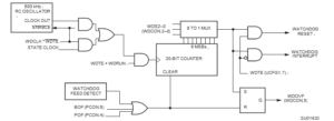
Block Diagram of the Watchdog Timer