Crack MCU AT89C51ID2 File
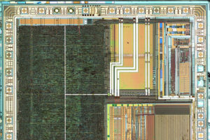
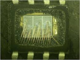
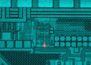
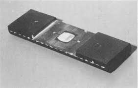
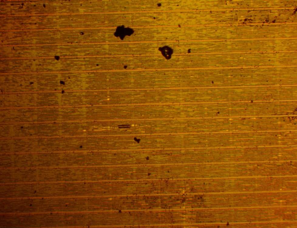
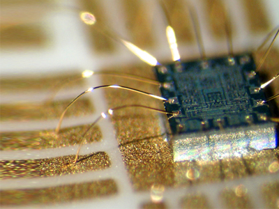
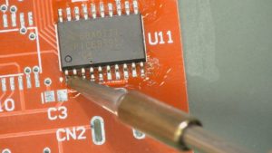
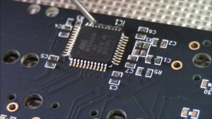
Crack MCU AT89C51ID2 secured memory and extract heximal File from microcontroller AT89C51ID2, reverse engineering processor AT89C51ID2 structure to locate the security fuse bit;
Each module in the PCA has a special function register associated with it. These registers are: CCAPM0 for module 0, CCAPM1 for module 1, etc. (See Table 28). The registers contain the bits that control the mode that each module will operate in.
The ECCF bit (CCAPMn.0 where n=0, 1, 2, 3, or 4 depending on the module) enables the CCF flag in the CCON SFR to generate an interrupt when a match or compare occurs in the associated module when retrieve silicon MCU C8051F530 code.
PWM (CCAPMn.1) enables the pulse width modulation mode. The TOG bit (CCAPMn.2) when set causes the CEX output associated with the module to toggle when there is a match between the PCA counter and the module’s capture/compare register.
The match bit MAT (CCAPMn.3) when set will cause the CCFn bit in the CCON register to be set when there is a match between the PCA counter and the module’s capture/compare register. The next two bits CAPN (CCAPMn.4) and CAPP (CCAPMn.5) determine the edge that a capture input will be active on. The CAPN bit enables the negative edge, and the CAPP bit enables the positive edge. If both bits are set both edges will be enabled and a capture will occur for either transition.
The last bit in the register ECOM (CCAPMn.6) when set enables the comparator function. There are two additional registers associated with each of the PCA modules. They are CCAPnH and CCAPnL and these are the registers that store the 16-bit count when a capture occurs or a compare should occur. When a module is used in the PWM mode these registers are used to control the duty cycle of the output (See Table 30 & Table 31) before Crack microcontroller ti 430g2452 memory.
To use one of the PCA modules in the capture mode either one or both of the CCAPM bits CAPN and CAPP for that module must be set. The external CEX input for the module (on port 1) is sampled for a transition. When a valid transition occurs the PCA hardware loads the value of the PCA counter registers (CH and CL) into the module’s capture registers (CCAPnL and CCAPnH). If the CCFn bit for the module in the CCON SFR and the ECCFn bit in the CCAPMn SFR are set then an interrupt will be generated.
Before enabling ECOM bit, CCAPnL and CCAPnH should be set with a non zero value, otherwise an unwanted match could happen. Writing to CCAPnH will set the ECOM bit. Once ECOM set, writing CCAPnL will clear ECOM so that an unwanted match doesn’t occur while modifying the compare value. Writing to CCAPnH will set ECOM. For this reason, user software should write CCAPnL first, and then CCAPnH. Of course, the ECOM bit can still be controlled by accessing to CCAPMn register.
In this mode the CEX output (on port 1) associated with the PCA module will toggle each time a match occurs between the PCA counter and the module’s capture registers.
To activate this mode the TOG, MAT, and ECOM bits in the module’s CCAPMn SFR must be set. A prior write must be done to CCAPnL and CCAPnH before writing the ECOMn bit. Before enabling ECOM bit, CCAPnL and CCAPnH should be set with a non zero value, otherwise an unwanted match could happen. Once ECOM set, writing CCAPnL will clear ECOM so that an unwanted match doesn’t occur while modifying the compare value. Writing to CCAPnH will set ECOM. For this reason, user software should write CCAPnL first, and then CCAPnH. Of course, the ECOM bit can still be controlled by accessing to CCAPMn register after Crack MCU.
Tags: crack mcu embedded archive,crack mcu embedded code,crack mcu embedded content,crack mcu embedded data,crack mcu embedded eeprom,crack mcu embedded file,crack mcu embedded firmware,crack mcu embedded information,crack mcu embedded memory,crack mcu embedded program


