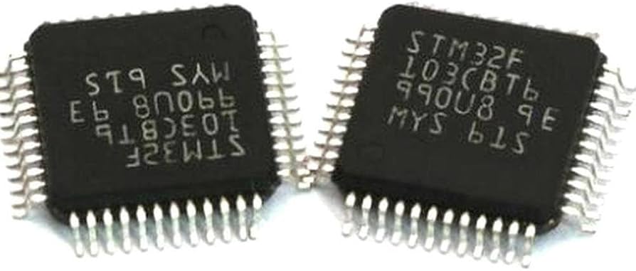
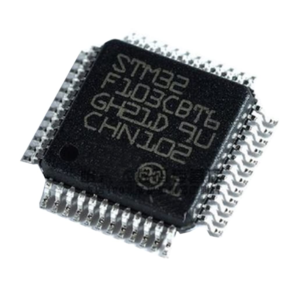
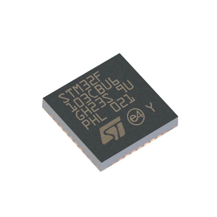
Crack STM32F103CB Microcontroller Flash Memory
Crack STM32F103CB microcontroller flash memory involves advanced techniques to access and decrypt the secured and encrypted firmware stored within its flash memory and EEPROM memory. This microcontroller unit (MCU) is equipped with protective features designed to safeguard its binary, heximal, and software data, making unauthorized access highly challenging. However, reverse engineering is often used to decode and restore essential programs and source code in legitimate cases, such as system recovery or hardware replication.
To decrypt the locked flash memory, experts analyze the microprocessor’s architecture and security protocols. Tools and techniques are employed to attack the encryption barriers and extract the stored data without damaging the microcomputer. This process enables the recovery of firmware crucial for maintaining or restoring operations in systems dependent on the STM32F103CB. By retrieving the binary and heximal data, engineers can restore or recreate the original program for reuse or troubleshooting.
Cracking the STM32F103CB’s flash memory also allows for the replication of its software. Cloning the firmware ensures that identical programs can be used in new devices or as backups for systems using this MCU. This is particularly useful in industrial applications where obsolescence or damage to original components could hinder functionality.
Reverse engineering such secured microprocessors requires precision to handle encrypted firmware while maintaining the integrity of the flash memory. Unlocking and restoring the firmware can be invaluable for resolving compatibility issues, replicating hardware designs, or ensuring the continuity of critical operations.
While the process to crack STM32F103CB microcontroller flash memory is technically demanding, it must always adhere to ethical and legal standards. Unauthorized decryption or replication of software is a violation of intellectual property rights. Proper compliance ensures that these techniques are used responsibly to recover, restore, and replicate programs in secure and lawful ways.
The low-speed external (LSE) clock can be supplied with a 32.768 kHz crystal/ceramic resonator oscillator by Crack STM32F103CB Microcontroller Flash Memory. All the information given in this paragraph are based on characterization results obtained with typical external components specified in below Table.
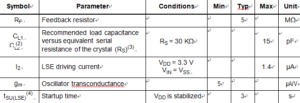
In the application, the resonator and the load capacitors have to be placed as close as possible to the oscillator pins in order to minimize output distortion and startup stabilization time after Unlock MC68HC705C8A MCU Flash Memory. Refer to the crystal resonator manufacturer for more details on the resonator characteristics (frequency, package, accuracy).
For CL1 and CL2 it is recommended to use high-quality ceramic capacitors in the 5 pF to 15 pF range selected to match the requirements of the crystal or resonator when Break IC Flash. CL1 and CL2, are usually the same size in the purpose of Crack NXP P87C552 Microcontroller Flash Memory. The crystal manufacturer typically specifies a load capacitance which is the series combination of CL1 and CL2.
Load capacitance CL has the following formula: CL = CL1 x CL2 / (CL1 + CL2) + Cstray where Cstray is the pin capacitance and board or trace PCB-related capacitance to facilitate the process of Break NXP MC908SR12 Microcontroller Flash. Typically, it is between 2 pF and 7 pF.
Caution: To avoid exceeding the maximum value of CL1 and CL2 (15 pF) it is strongly recommended to use a resonator with a load capacitance CL £ 7 pF. Never use a resonator with a load capacitance of 12.5 pF.
Example: if you choose a resonator with a load capacitance of CL = 6 pF, and Cstray = 2 pF, then CL1 = CL2 = 8 pF.