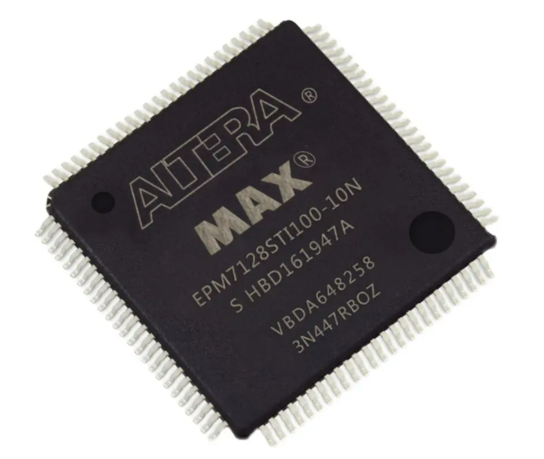
Unlock Altera CPLD EPM7128BUC Processor
Unlock Altera CPLD EPM7128BUC Processor is a process to attack cpld epm7128 tamper resistance system and readout embedded firmware jed file from CPLD chip;
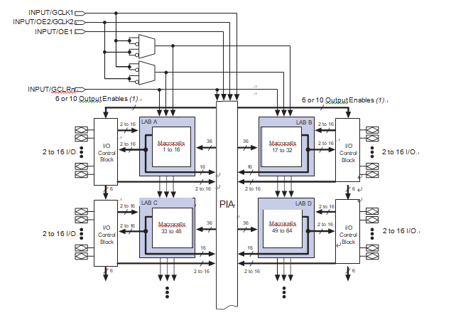
The MAX 7000A architecture includes the following elements:
- Logic array blocks (LABs)
- Macrocells
- Expander product terms (shareable and parallel)
- Programmable interconnect array
- I/O control blocks
The MAX 7000A architecture includes four dedicated inputs that can be used as general-purpose inputs or as high-speed, global control signals (clock, clear, and two output enable signals) for each macrocell and I/O pin. Below Figure shows the architecture of MAX 7000A devices.
Note:
- EPM7032AE, EPM7064AE, EPM7128A, EPM7128AE, EPM7256A, and EPM7256AE devices have six output enables. EPM7512AE devices have 10 output enables.
Logic Array Blocks
The MAX 7000A device architecture is based on the linking of
high-performance LABs. LABs consist of 16-macrocell arrays, as shown in above Figure. Multiple LABs are linked together via the PIA, a global bus that is fed by all dedicated input pins, I/O pins, and macrocells.
Each LAB is fed by the following signals:
- 36 signals from the PIA that are used for general logic inputs
- Global controls that are used for secondary register functions
- Direct input paths from I/O pins to the registers that are used for fast setup times