Replicate MCU PIC16LF639 Chip Eeprom Data
Replicate MCU PIC16LF639 chip eeprom data and microchip flash memory program starts from decrypt locked microcontroller PIC16LF639 read-out protection, extract embedded firmware in the format of binary file or heximal data from secured microprocessor PIC16LF639;
When program memory is code-protected, the microcontroller can read and write to program memory normally as well as execute instructions to Replicate MCU PIC16LF639 Chip Eeprom Data. Writes by the device may be selectively inhibited to regions of the memory depending on the setting of bits by MCU Reading, WRT1:WRT0, of the Configuration Word (see Section 12.1 “Configuration Bits” for additional information). External access to the memory is also disabled same as Pull MCU Chip Microchip PIC18F2455.
The PIC16LF639 can be operated in eight different oscillator modes. The user can program three configu- ration bits (FOSC2:FOSC0) to select one of these eight modes (modes 5-8 are new PIC16 oscillator configurations):
1. LP Low-Power Crystal
2. XT Crystal/Resonator
3. HS High-Speed Crystal/Resonator
4. RC External Resistor/Capacitor with
FOSC/4 output on RA6
5. RCIO External Resistor/Capacitor with
I/O on RA6
6. INTIO1 Internal Oscillator with FOSC/4
output on RA6 and I/O on RA7
7. INTIO2 Internal Oscillator with I/O on RA6
and RA7
8. ECIO External Clock with I/O on RA6
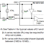
In XT, LP or HS modes, a crystal or ceramic resonator is connected to the OSC1/CLKI and OSC2/CLKO pins to establish oscillation (see below Figures). The PIC16LF639 oscillator design requires the use of a parallel cut crystal. Use of a series cut crystal may give a frequency out of the crystal manufacturer’s specifications in the process of Copy MCU PIC16F74 Eeprom.
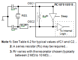
Capacitor values are for design guidance only.
These capacitors were tested with the crystals listed below for basic start-up and operation when Replicate MCU PIC16LF639 Chip Eeprom Data. These values were not optimized.
Different capacitor values may be required to produce acceptable oscillator operation to facilitate the process of Crack Microcontroller PIC16LF677 Firmware. The user should test the performance of the oscillator over the expected VDD and temperature range for the application.
See the notes following this table for additional information.
Note 1: Higher capacitance increases the stability of the oscillator but also increases the start-up time.
2: Since each crystal has its own character- istics, the user should consult the crystal manufacturer for appropriate values of external components.
3: RS may be required in HS mode, as well as XT mode, to avoid overdriving crystals with low drive level specification.
4: Always verify oscillator performance over the VDD and temperature range that is expected for the application.