NXP P89LPC908 Chip Secured Code Cracking
NXP P89LPC908 Chip Secured Code Cracking starting from compromise the timer/counter, The two 16-bit Timer/Counter registers: Timer 0 and Timer 1 can be configured to operate either as timers or event counters (see below Table).
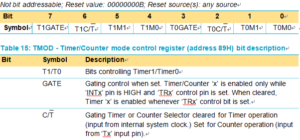
Timer &or Counter mode control register(address 89H)bit allocation
In the ‘Timer’ function, the register is incremented every machine cycle. Thus, one can think of it as counting machine cycles. Since a machine cycle consists of six oscillator periods, the count rate is 1¤6 of the oscillator frequency which can be applied for MCU Code reading.
In the ‘Counter’ function, the register is incremented in response to a 1-to-0 transition at its corresponding external input pin, T0 or T1. In this function, the external input is sampled once every machine cycle.
When the samples show a high in one cycle and a low in the next cycle, the count is incremented. The new count value appears in the register in the machine cycle following the one in which the transition was detected in order to Get Microcontroller P89C536 Embedded Firmware.
Since it takes two machine cycles (12 oscillator periods) for 1-to-0 transition to be recognized, the maximum count rate is 1¤12 of the oscillator frequency.
NXP P89LPC908 Chip Secured Code Cracking
There are no restrictions on the duty cycle of the external input signal, but to ensure that a given level is sampled at least once before it changes, it should be held for at least one full machine cycle. In addition to the ‘Timer’ or ‘Counter’ selection, Timer 0 and Timer 1 have four operating modes from which to select.
The ‘Timer’ or ‘Counter’ function is selected by control bits C/T in the Special Function Register TMOD. These two Timer/Counters have four operating modes, which are selected by bit-pairs (M1, M0) in TMOD. Modes 0, 1, and 2 are the same for both Timers/Counters to carry out Philip MCU P89V51RB2 Program Memory Extraction. Mode 3 is different. The four operating modes are described in the following text.