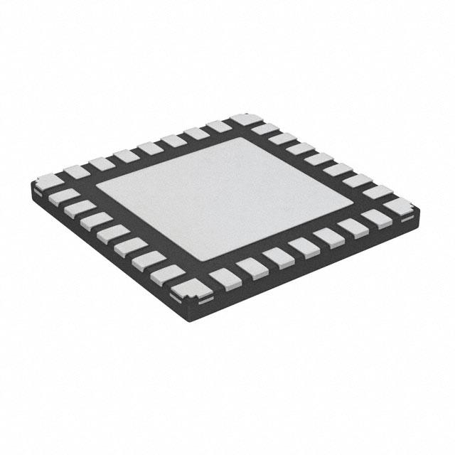
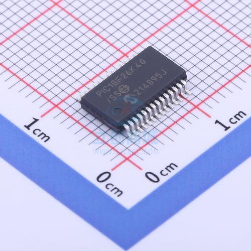
Microcontroller PIC18F26K40T Locked Flash Memory Unlocking
Microcontroller PIC18F26K40T Locked Flash Memory Unlocking is a process to hack microchip mcu pic18f26k80 secured flash memory, encrypted heximal file will be copied from pic18f26k40t;

In Half-Bridge mode, two output signals are generated as true and inverted versions of the input as illustrated in Figure 26-2. A non-overlap (dead-band) time is inserted between the two outputs as described in Section 26.6 “Dead-Band Control”.
The output steering feature cannot be used in this mode. A basic block dia- gram of this mode is shown in Figure 26-1. The unused outputs CWGxC and CWGxD drive similar signals as CWGxA and CWGxB to crack microchip processor pic18lf252 memory, with polarity inde- pendently controlled by the POLC and POLD bits of the CWGxCON1 register, respectively.

In Push-Pull mode, two output signals are generated, alternating copies of the input as illustrated in Figure 26-4. This alternation creates the push-pull effect required for driving some transformer-based power supply designs. Steering modes are not used in Push-Pull mode. A basic block diagram for the Push-Pull mode is shown in Figure 26-3.
The push-pull sequencer is reset whenever EN = 0 or if an auto-shutdown ccurs. The sequencer is clocked by the first input pulse when clone pic18f1220t microcontroller firmware, and the first output appears on CWGxA. The unused outputs CWGxC and CWGxD drive copies of CWGxA and CWGxB, respectively, but with polarity controlled by the POLC and POLD bits of the CWGxCON1 register, respectively.
Tags: læse op beskyttet mikrocontroller eeprom heksimale data,læse op krypteret MCU IC indlejret firmwareprogram,læse op låst mikroprocessor flashhukommelsessoftware,læse op sikret mikrocomputer hukommelse binær fil

