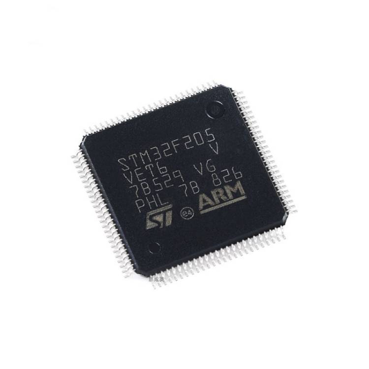
Dump STM32F205VE Microcontroller Flash Memory Heximal
Dump STM32F205VE Microcontroller Flash Memory Heximal after breaking off stm32f205ve flash memory protection and copy arm cortex3 stm32f205ve flash embedded program;
The STM32F20x family supports three low-power modes to achieve the best compromise between low-power consumption, short startup time and available wakeup sources:
· Sleep mode
In Sleep mode, only the CPU is stopped. All peripherals continue to operate and can wake up the CPU when an interrupt/event occurs.
· Stop mode
The Stop mode achieves the lowest power consumption while retaining the contents of SRAM and registers. All clocks in the 1.2 V domain are stopped, the PLL, the HSI RC and the HSE crystal oscillators are disabled by cracking arm mcu stm32f205rb protective system. The voltage regulator can also be put either in normal or in Low-power mode.
The device can be woken up from the Stop mode by any of the EXTI line. The EXTI line source can be one of the 16 external lines, the PVD output, the RTC alarm / wakeup / tamper / time stamp events, the USB OTG FS/HS wakeup or the Ethernet wakeup.
· Standby mode
The Standby mode is used to achieve the lowest power consumption. The internal voltage regulator is switched off so that the entire 1.2 V domain is powered off. The PLL, the HSI RC and the HSE crystal oscillators are also switched off. After entering Standby mode to unlock stm32f205rc secured microcontroller flash program, the SRAM and register contents are lost except for registers in the backup domain and the backup SRAM when selected.
The device exits the Standby mode when an external reset (NRST pin), an IWDG reset, a rising edge on the WKUP pin, or an RTC alarm / wakeup / tamper /time stamp event occurs.
Note: The RTC, the IWDG, and the corresponding clock sources are not stopped when the device enters the Stop or Standby mode.