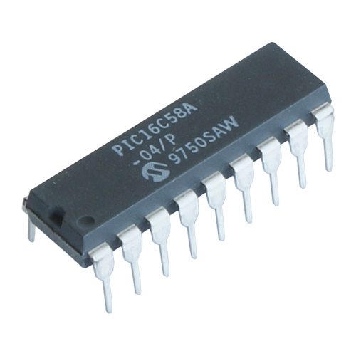
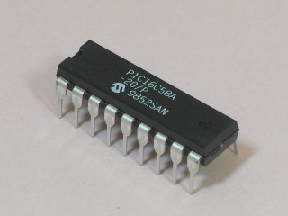
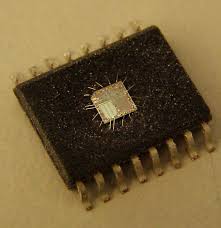
Crack PIC16C58A MCU Flash Memory
Crack PIC16C58A MCU flash memory and locked eeprom memory starts from reverse engineering PIC16C58A secured microcontroller tamper resistance system, read encrypted embedded firmware of binary file or heximal data out from protective PIC16C58A microprocessor;
The sequence of instructions should allow the pin voltage to stabilize (load dependent) before the next instruction, which causes that file to be read into the CPU, is executed in the process of Motorola MC68HC08AS20 MCU Flash Copying. Otherwise, the previous state of that pin may be read into the CPU rather than the new state when it will be used for Crack PIC16C58A MCU Flash Memory. When in doubt, it is better to separate these instructions with a NOP or another instruction not accessing this I/O port to Break IC Flash.

The Timer0 module has the following features:
• 8-bit timer/counter register, TMR0
– Readable and writable
• 8-bit software programmable prescaler
• Internal or external clock select
– Edge select for external clock
Below Figure is a simplified block diagram of the Timer0 module.
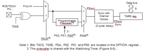
Timer mode is selected by clearing the T0CS bit (OPTION<5>). In timer mode, the Timer0 module will increment every instruction cycle (without prescaler) by Extract Philip MCU P87C752 Memory Code. If TMR0 register is written, the increment is inhibited for the following two cycles. The user can work around this by writing an adjusted value to the TMR0 register.
Counter mode is selected by setting the T0CS bit (OPTION<5>). In this mode, Timer0 will increment either on every rising or falling edge of pin T0CKI. The T0SE bit (OPTION<4>) determines the source edge. Clearing the T0SE bit selects the rising edge from Crack STM32F103CB Microcontroller Flash Memory. Restrictions on the external clock input are discussed in detail in Section 6.1. The prescaler may be used by either the Timer0 module or the Watchdog Timer, but not both.
The prescaler assignment is controlled in software by the control bit PSA (OPTION<3>). Clearing the PSA bit will assign the prescaler to Timer0. The prescaler is not readable or writable. When the prescaler is assigned to the Timer0 module, prescale values of 1:2, 1:4,…, 1:256 are selectable. Section 6.2 details the operation of the prescaler.
When an external clock input is used for Timer0, it must meet certain requirements for the purpose of Decode Microprocessor IC Microchip PIC18F258. The external clock requirement is due to internal phase clock (TOSC) synchronization. Also, there is a delay in the actual incrementing of Timer0 after synchronization.