Crack Philip Microcomputer P87C54 Eeprom Memory Code
Crack Philip Microcomputer P87C54 Eeprom Memory Code need to start from understand the structure of Eeprom and how the eeprom can be programmed. first of all let’s discuss how the low voltage eprom operation:
The EPROM array contains some analog circuits that are not required when VDD is less than 4 V, but are required for a VDD greater than 4 V. The LPEP bit (AUXR.4), when set by software, will power down these analog circuits resulting in a reduced supply current. LPEP is cleared only by power-on reset, so it may be set
ONLY for applications that always operate with VDD less than 4 V.
The P87C54 has an integrated power-on reset circuit which always provides a reset when power is initially applied to the device only after IC breaking has been done. It is recommended to use the internal reset whenever possible to save external components and to be able to use pin P1.5 as a general-purpose input pin.
Crack Philip Microcomputer P87C54 Eeprom Memory Code
The P87C54 can additionally be configured to use P1.5 as an external active-low reset pin RST by programming the RPD bit in the User Configuration Register UCFG1 to 0. The internal reset is still active on power-up of the device. While the signal on the RST pin is low, the P87C54 is held in reset until the signal goes high.
The watchdog timer on the P87C54 can act as an oscillator fail detect because it uses an independent, fully on-chip oscillator. UCFG1 is described in the System Configuration Bytes section of this datasheet.
The P87C54 has two general purpose counter/timers which are upward compatible with the standard 80C51 Timer 0 and Timer 1 to facilitate by Philip Microcontroller P87C750 Eeprom Data unlocking. Both can be configured to operate as timers or can be configured to be an event counter (see BELOW Figure). An option to automatically toggle the T0 pin upon timer overflow has been added.
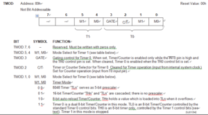
Timer-Counter Mode Control Register (TMOD)
In the “Timer” function, the register is incremented every machine cycle. Thus, one can think of it as counting machine cycles. Since a machine cycle consists of 6 CPU clock periods, the count rate is 1/6 of the CPU clock frequency. Refer to the section Enhanced CPU for a description of the CPU clock.