Crack Microcontroller dsPIC30F3012 Heximal
Crack Microcontroller dsPIC30F3012 Heximal from its secure memory, the heximal will be copied to other blank MCU to make the perfect clone MCU units, provide the same functions as originals;
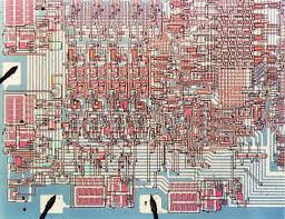
Crack Microcontroller dsPIC30F3012 Heximal
Refer to Section 4.0 for details on modulo and bit-reversed addressing.
The core supports Inherent (no operand), Relative, Literal, Memory Direct, Register Direct, Register Indirect, Register Offset and Literal Offset Addressing modes. Instructions are associated with predefined Addressing modes, depending upon their functional requirements.
For most instructions, the core is capable of executing a data (or program data) memory read and MCU flash reading, a working register (data) read, a data memory write and a program (instruction) memory read per instruction cycle. As a result, 3-operand instructions are supported, allowing C = A+B operations to be executed in a single cycle.
A DSP engine has been included to significantly enhance the core arithmetic capability and throughput. It features a high speed 17-bit by 17-bit multiplier, a 40-bit ALU, two 40-bit saturating accumulators and a 40-bit bidirectional barrel shifter. Data in the accumulator or any working register can be shifted up to 15 bits.
right, or 16 bits left in a single cycle. The DSP instructions operate seamlessly with all other instructions and have been designed for optimal real-time performance. The MAC class of instructions can concurrently fetch two data operands from memory while multiplying two W registers. To enable this concurrent fetching of data operands, the data space has been split for these instructions and linear for all others.
This has been achieved in a transparent and flexible manner, by dedicating certain working registers to each address space for the MAC class of instructions. The core does not support a multi-stage instruction pipeline. However, a single stage instruction pre-fetch mechanism is used, which accesses and partially decodes instructions a cycle ahead of execution, in order to maximize available execution time.
Most instructions execute in a single cycle with certain exceptions. The core features a vectored exception processing structure for traps and interrupts, with 62 independent vectors. The exceptions consist of up to 8 traps (of which 4 are reserved) and 54 interrupts. Each interrupt is prioritized based on a user assigned priority between 1 and 7 (1 being the lowest priority and 7 being the highest), in conjunction with a predetermined ‘natural order’. Traps have fixed priorities ranging from 8 to 15.
The programmer’s model is shown in Figure 2-1 and consists of 16 x 16-bit working registers (W0 through W15), 2 x 40-bit accumulators (AccA and AccB), STATUS register (SR), Data Table Page register (TBLPAG), Program Space Visibility Page register (PSVPAG), DO and REPEAT registers (DOSTART, DOEND, DCOUNT and RCOUNT) and Program Counter (PC). The working registers can act as data, address or offset registers. All registers are memory mapped.
W0 acts as the W register for file register addressing. Some of these registers have a shadow register associated with each of them, as shown in Figure 2-1. The shadow register is used as a temporary holding register and can transfer its contents to or from its host register upon the occurrence of an event.
None of the shadow registers are accessible directly. The following rules apply for transfer of registers into and out of shadows. When a byte operation is performed on a working register, only the Least Significant Byte of the target register is affected. However, a benefit of memory mapped working registers is that both the Least and Most Significant Bytes can be manipulated through byte wide data memory space accesses.
The dsPIC® devices contain a software stack. W15 is the dedicated software Stack Pointer (SP), and will be automatically modified by exception processing and subroutine calls and returns. However, W15 can be referenced by any instruction in the same manner as all other W registers.
This simplifies the reading, writing and manipulation of the stack pointer (e.g., creating stack frames).
Tags: crack microcontroller binary archive,crack microcontroller binary code,crack microcontroller binary content,crack microcontroller binary data,crack microcontroller binary eeprom,crack microcontroller binary file,crack microcontroller binary firmware,crack microcontroller binary information,crack microcontroller binary memory,crack microcontroller binary program


