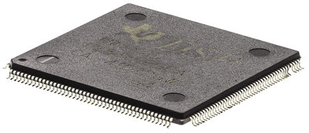
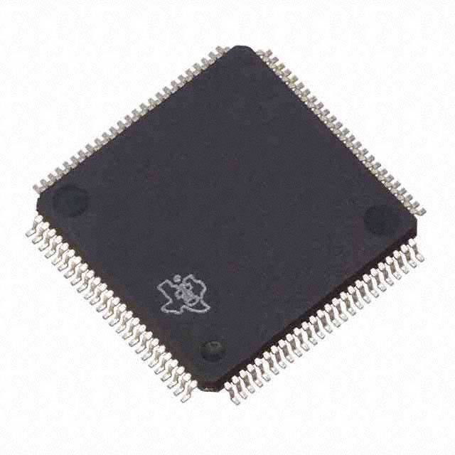
Crack DSP TMS320F28030PN Microcontroller Flash Memory
Crack DSP TMS320F28030PN Microcontroller Flash Memory and copy tms320f28030pn mcu flash program to new chip which will provide the exact same functions as originals;

JTAG test reset with internal pulldown. TRST, when driven high, gives the scan system control of the operations of the device. If this signal is not connected or driven low to restoring dsp cpu tms320f28030pagt source code, the device operates in its functional mode, and the test reset signals are ignored.
NOTE: TRST is an active high test pin and must be maintained low at all times during normal device operation. An external pulldown resistor is required on this pin. The value of this resistor should be based on drive strength of the debugger pods applicable to the design.
A 2.2-kΩ resistor generally offers adequate protection. Because this is application-specific, TI recommends validating each target board for proper operation of the debugger and the application. (↓)

See GPIO18. Output clock derived from SYSCLKOUT. XCLKOUT is either the same frequency, one-half the frequency, or one-fourth the frequency of SYSCLKOUT. This is controlled by bits 1:0 (XCLKOUTDIV) in the XCLK register.
At reset, XCLKOUT = SYSCLKOUT/4. The XCLKOUT signal can be turned off by setting XCLKOUTDIV to 3. The mux control for GPIO18 must also be set to XCLKOUT for this signal to propogate to the pin.
Tags: атака DSP TMS320F28030PN Микроконтроллерная флэш-память,разрыв флэш-памяти микроконтроллера DSP TMS320F28030PN,трещина DSP TMS320F28030PN Флэш-память микроконтроллера

