Clone Microprocessor PIC16LF76 Flash Program
Clone microprocessor PIC16LF76 flash program after unlock protective microcontroller PIC16LF76 readout-tamper resistance, restore microchip secured MCU PIC16LF76 embedded firmware as binary source code or heximal data file;
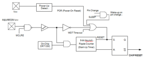
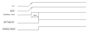
The Power-On Reset circuit and the Device Reset Timer (Section 7.5) circuit are closely related by Clone Microprocessor PIC16LF76 Flash Program. On power-up, the reset latch is set and the DRT is reset. The DRT timer begins counting once it detects MCLR to be high. After the time-out period, which is typically 18 ms, it will reset the reset latch and thus end the on-chip reset signal after Restore DSP CPU TMS320F28030PAGT Source Code.
A power-up example where MCLR is held low is shown in below Figure.
VDD is allowed to rise and stabilize before bringing MCLR high. The chip will actually come out of reset TDRT msec after MCLR goes high in the process of Recover MCU Firmware. In below Figure, the on-chip Power-On Reset feature is being used (MCLR and VDD are tied together or the pin is programmed to be RB3.). The VDD is stable before the start-up timer times out and there is no problem in getting a proper reset after Clone STM32F100R6 ARM MCU Code.
However, Figure 7- 11 depicts a problem situation where VDD rises too slowly for the purpose of Crack Philip P89C51RD2H MCU Locked Eeprom. The time between when the DRT senses that MCLR is high and when MCLR (and VDD) actually reach their full value, is too long.
In this situation, when the start-up timer times out, VDD has not reached the VDD (min) value and the chip is, therefore, not guaranteed to function correctly. For such situations, we recommend that external RC circuits be used to achieve longer POR delay times to better support the process of Copy Protected PIC12C509A Code.