Clone Microprocessor ATmega1281P Flash
Clone Microprocessor ATmega1281P Flash program and eeprom data, the firmware recoverd from MCU ATmega1281P will be the same as original version after break the protection away;
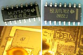
Clone Microprocessor ATmega1281P Flash program and eeprom data, the firmware recoverd from MCU ATmega1281P will be the same as original version after break the protection away
A 50% duty cycle clock can be programmed to come out on P1.0, as shown in Figure 5. This pin, besides being a regular I/0 pin, has two alternate functions. It can be programmed to input the external clock for Timer/Counter 2 or to output a 50% duty cycle clock ranging from 61 Hz to 4 MHz at a 16 MHz operating frequency.
To configure the Timer/Counter 2 as a clock generator, bit C/T2 (T2CON.1) must be cleared and bit T2OE (T2MOD.1) must be set. Bit TR2 (T2CON.2) starts and stops the timer. The clock-out frequency depends on the oscillator frequency and the reload value of Timer 2 capture registers (RCAP2H, RCAP2L), as shown in the following equation.
In the clock-out mode, Timer 2 rollovers will not generate an interrupt. This behavior is similar to when Timer 2 is used as a baud-rate generator. It is possible to use Timer 2 as a baud-rate generator and a clock generator simultaneously.
Note, however, that the baud-rate and clock-out frequencies cannot be determined independently from one another since they both use RCAP2H and RCAP2L.
The UART in the ATMEGA1281P operates the same way as the UART in the ATMEGA1281P. For further information, see the October 1995 Microcontroller Data Book, page 2-49, section titled, “Serial Interface.”
The serial peripheral interface (SPI) allows high-speed synchronous data transfer between the ATMEGA1281P and peripheral devices or between several AT89S53 devices. The ATMEGA1281P SPI features include the following:
- Full-Duplex, 3-Wire Synchronous Data Transfer
- Master or Slave Operation
- 1.5-MHz Bit Frequency (max.)
- LSB First or MSB First Data Transfer
- Four Programmable Bit Rates
- End of Transmission Interrupt Flag
- Write Collision Flag Protection
· Wakeup from Idle Mode (Slave Mode Only)
Tags: clone microprocessor archive,clone microprocessor binary,clone microprocessor code,clone microprocessor content,clone microprocessor data,clone microprocessor eeprom,clone microprocessor file,clone microprocessor firmware,clone microprocessor heximal,clone microprocessor information,clone microprocessor memory,clone microprocessor program