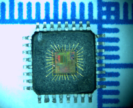
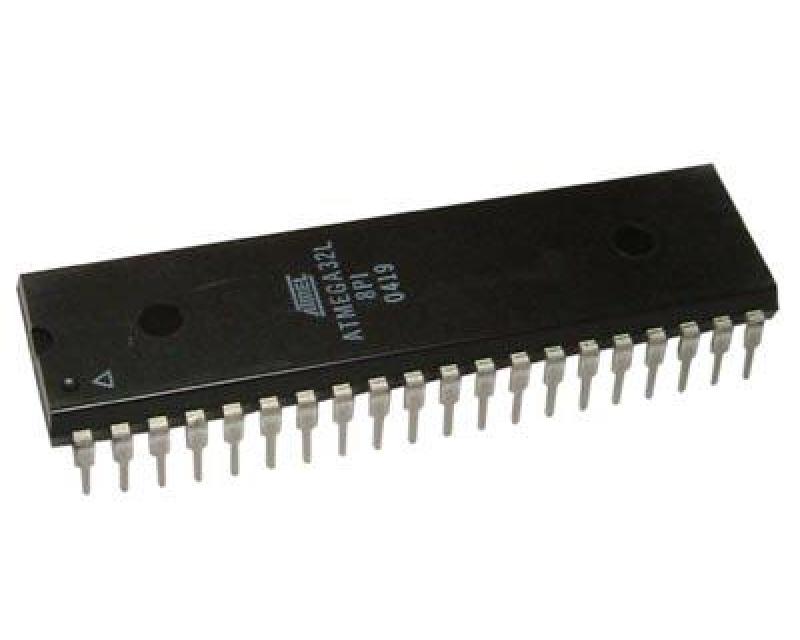
Clone ATmega32L Microprocessor Memory Data
Clone ATmega32L Microprocessor Memory Data and copy software file to new atmega32l mcu, the embedded firmware of microcontroller atmega32L will be readout;
The I/O space definition of the ATmega8A is shown in “Register Summary” on page 308. All ATmega8A I/Os and peripherals are placed in the I/O space. The I/O locations are accessed by the IN and OUT instructions, transferring data between the 32 general purpose working registers and the I/O space.
I/O Registers within the address range 0x00 – 0x1F are directly bit-accessible using the SBI and CBI instructions. In these registers, the value of single bits can be checked by using the SBIS and SBIC instructions to pull atmega32l microcontroller content out from its flash memory. Refer to the instruction set section for more details.
When using the I/O specific commands IN and OUT, the I/O addresses 0x00 – 0x3F must
be used. When addressing I/O Registers as data space using LD and ST instructions, 0x20 must be added to these addresses.
For compatibility with future devices, reserved bits should be written to zero if accessed. Reserved I/O memory addresses should never be written.
Some of the Status Flags are cleared by writing a logical one to them. Note that the CBI and SBI instructions will operate on all bits in the I/O Register by breaking off avr chip atmega32 mcu, writing a one back into any flag read as set, thus clearing the flag.
The CBI and SBI instructions work with registers 0x00 to 0x1F only. The I/O and Peripherals Control Registers are explained in later sections.
Tags: klon chroniony plik oprogramowania mikrokomputera,klon szyfrowany program szesnastkowy mikrokontrolera,klon zabezpieczony kod firmware mikroprocesora,klon zablokowana binarna pamięć flash chipa MCU