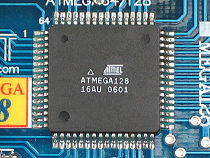
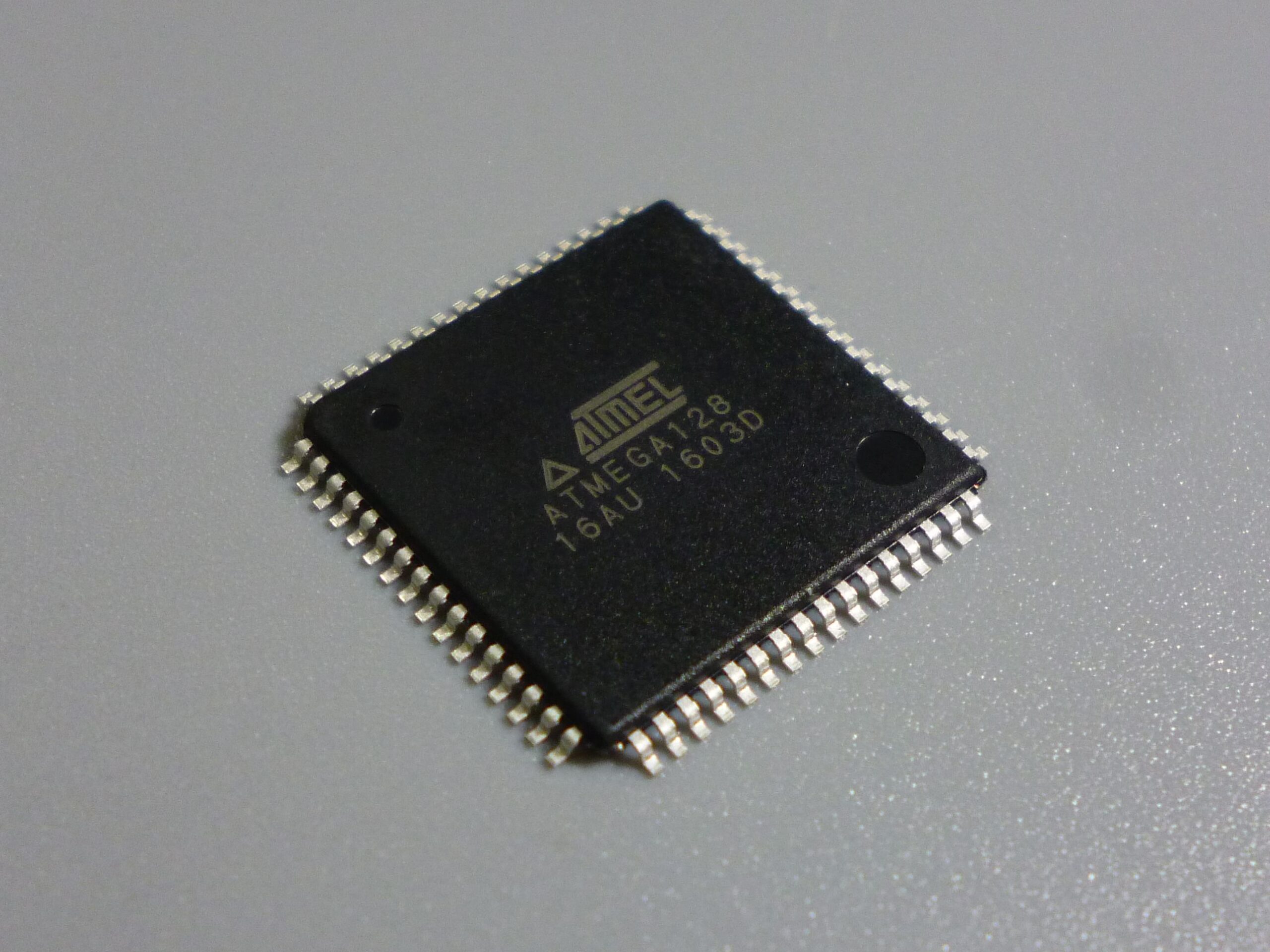
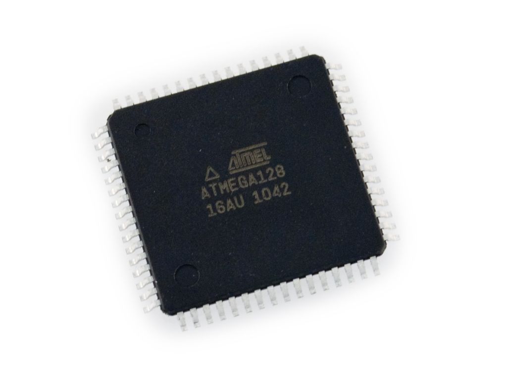
AVR Microcontroller ATMEGA128 Source Code Cloning
AVR Microcontroller ATMEGA128 Source Code Cloning starts from break atmega128 mcu chip protection flash system and then extract atmega128 microprocessor firmware from flash memory;
An External Reset is generated by a low level on the RESET pin. Reset pulses longer than the minimum pulse width (see Table 15 on page 38) will generate a reset, even if the clock is not running. Shorter pulses are not guaranteed to generate a reset to unlock secured microprocessor atmega1280 flash memory. When the applied signal reaches the Reset Threshold Voltage – VRST on its positive edge, the delay counter starts the MCU after the time-out period tTOUT has expired.
ATmega8 has an On-chip Brown-out Detection (BOD) circuit for monitoring the VCC level during operation by comparing it to a fixed trigger level. The trigger level for the BOD can be selected by the fuse BODLEVEL to be 2.7V (BODLEVEL unprogrammed), or 4.0V (BODLEVEL pro- grammed). The trigger level has a hysteresis to ensure spike free Brown-out Detection. The hysteresis on the detection level should be interpreted as VBOT+ = VBOT + VHYST/2 and VBOT- = VBOT – VHYST/2.
The BOD circuit can be enabled/disabled by the fuse BODEN. When the BOD is enabled (BODEN programmed), and VCC decreases to a value below the trigger level (VBOT- in Figure 18), the Brown-out Reset is immediately activated to pull secured mcu chip atmega1281 software out from its flash memory. When VCC increases above the trigger level (VBOT+ in Figure 18), the delay counter starts the MCU after the time-out period tTOUT has expired.
The BOD circuit will only detect a drop in VCC if the voltage stays below the trigger level for lon- ger than tBOD given in Table 15 on page 38.
Tags: clonar o código-fonte do microcontrolador AVR ATMEGA128,copie o código fonte do microcontrolador AVR ATMEGA128,duplicar o código fonte do microcontrolador AVR ATMEGA128,replicar o código-fonte ATMEGA128 do microcontrolador AVR