-
Product Categories
Live Support Chat


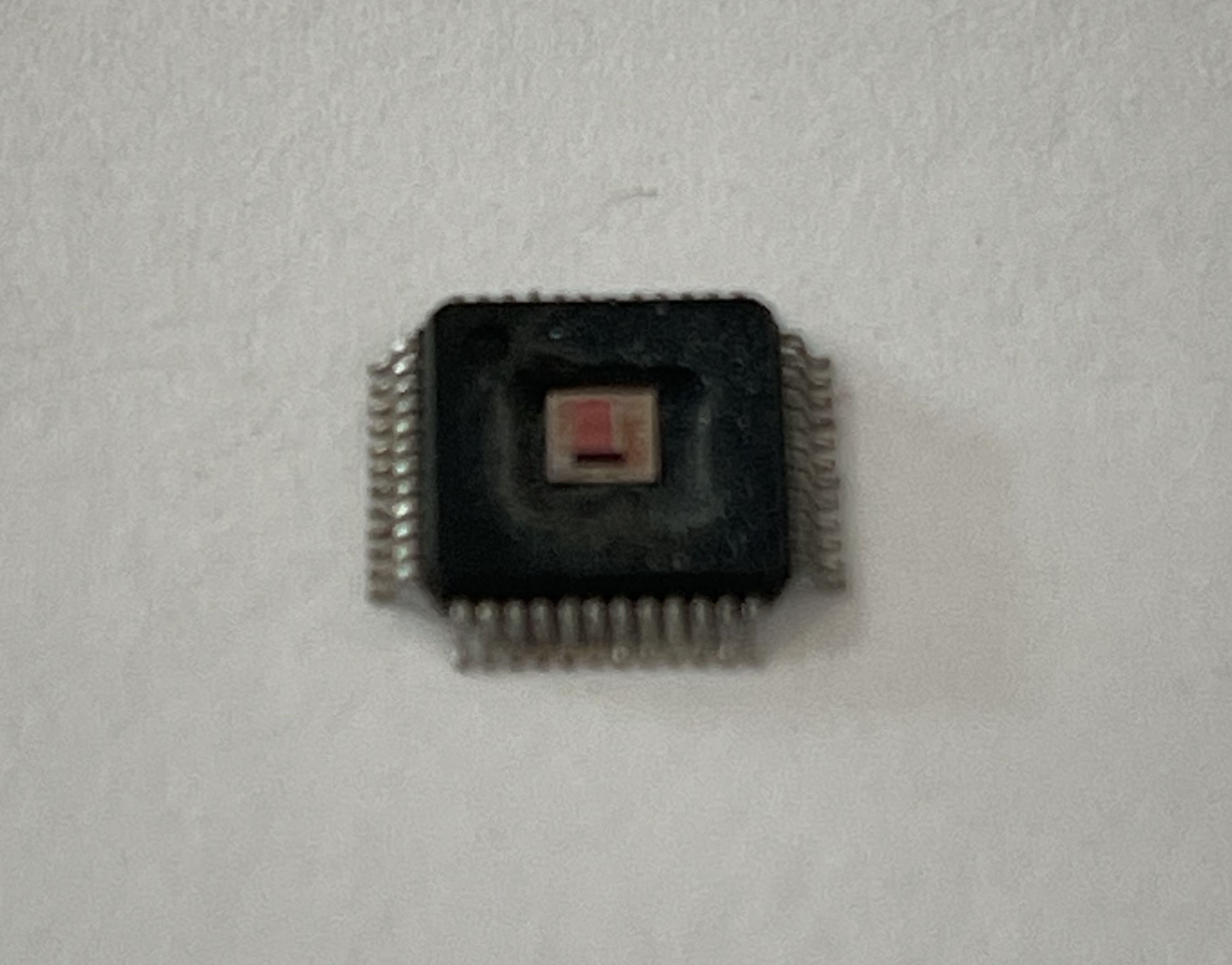
ARM Microprocessor STM32F070CB Flash Memory Cracking
ARM Microprocessor STM32F070CB Flash Memory Cracking is a process to attack mcu stm32f070cb locked bit by focus ion beam technique and then copy flash memory program to new cpu stm32f070cb processor;
In addition to the internal peripheral current consumption measured previously (see
Table 31: Peripheral current consumption), the I/Os used by an application also contribute to the current consumption. When an I/O pin switches, it uses the current from the I/O supply voltage to supply the I/O pin circuitry and to charge/discharge the capacitive load (internal or external) connected to the pin:
ISW =
VDDIOx ´ fSW ´ C
where
ISW is the current sunk by a switching I/O to charge/discharge the capacitive load VDDIOx is the I/O supply voltage
fSW is the I/O switching frequency
C is the total capacitance seen by the I/O pin: C = CINT + CEXT + CS CS is the PCB board capacitance including the pad pin.
The test pin is configured in push-pull output mode and is toggled by software at a fixed frequency after attacking arm microcontroller stm32f051c4 flash memory.
The current consumption of the on-chip peripherals is given in Table 31. The MCU is placed under the following conditions:
- All I/O pins are in analog mode
- All peripherals are disabled unless otherwise mentioned
- The given value is calculated by measuring the current consumption
- with all peripherals clocked off
- with only one peripheral clocked on
- Ambient operating temperature and supply voltage conditions summarized in Table 17: Voltage characteristics