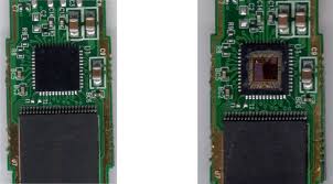
Unlock Microcontroller TS80C58X2 Binary
We can Unlock Microcontroller TS80C58X2 Binary, please view the Microcontroller TS80C58X2 features for your reference:
The prescaler assignment is fully under software control (i.e., it can be changed “on-the-fly” during program execution). To avoid an unintended device Reset, the following instruction sequence (Example 7-1) must be executed when changing the prescaler assignment from Timer0 to the WDT when Unlock Microcontroller.
To change the prescaler from the WDT to the Timer0 module, use the sequence shown in Example 7.2. This sequence must be used even if the WDT is disabled. A CLRWDT instruction should be executed before switching the prescaler if Unlock Microcontroller.
The comparator module contains one Analog comparator. The inputs to the comparator are multiplexed with GP0 and GP1 pins. The output of the comparator can be placed on GP2 after Unlock Microcontroller.
The CMCON0 register, shown in Register 8-1, controls the comparator operation. A block diagram of the comparator is shown in Figure 8-1. Overrides T0CS bit for TRIS control of GP2 before Unlock Microcontroller.
When the comparator is turned on, these control bits assert themselves. When the comparator is off, these bits have no effect on the device operation and the other control registers have precedence if Unlock Microcontroller.
The on-board comparator inputs, (GP0/CIN+, GP1/ CIN-), as well as the comparator output (GP2/COUT), are steerable. The CMCON0, OPTION and TRIS registers are used to steer these pins (see Figure 8-1) when Unlock Microcontroller.
If the Comparator mode is changed, the comparator output level may not be valid for the specified mode change delay shown in Table 12-1 if Unlock Microcontroller.
A single comparator is shown in Figure 8-2 along with the relationship between the analog input levels and the digital output. When the analog input at VIN+ is less than the analog input VIN-, the output of the comparator is a digital low level when Unlock Microcontroller.
When the analog input at VIN+ is greater than the analog input VIN-, the output of the comparator is a digital high level. The shaded areas of the output of the comparator in Figure 8-2 represent the uncertainty due to input offsets and response time after Unlock Microcontroller.
Tags: unlock microcontroller binary archive,unlock microcontroller binary code,unlock microcontroller binary content,unlock microcontroller binary data,unlock microcontroller binary eeprom,unlock microcontroller binary file,unlock microcontroller binary firmware,unlock microcontroller binary information,unlock microcontroller binary memory,unlock microcontroller binary program


