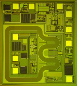
Unlock Microcontroller ATtiny461V Binary
Unlock Microcontroller ATtiny461V embedded memory and cut off the protective fuse bit, disable the tamper resistance system then readout the Binary or heximal from it, the functionality will be intact during the process of IC breaking to ensure the extracted program can be exactly the same as originals;

Unlock Microcontroller ATtiny461V embedded memory and cut off the protective fuse bit, disable the tamper resistance system then readout the Binary or heximal from it
The ATtiny461v AVR is supported with a full suite of program and system development tools including: C Compilers, Macro Assemblers, Program Debugger/Simulators, In-Circuit Emulators, and Evaluation kits. A comprehensive set of drivers, application notes, data sheets and descriptions on development tools are available for download.
This documentation contains simple code examples that briefly show how to use various parts of the device. These code examples assume that the part specific header file is included before compilation.
Be aware that not all C compiler vendors include bit definitions in the header files and interrupt handling in C is compiler dependent. Please confirm with the C compiler documentation for more details. For I/O Registers located in the extended I/O map, “IN”, “OUT”, “SBIS”, “SBIC”, “CBI”, and “SBI” instructions must be replaced with instructions that allow access to extended I/O. Typically, this means “LDS” and “STS” combined with “SBRS”, “SBRC”, “SBR”, and “CBR”.
Note that not all AVR devices include an extended I/O map. Reliability Qualification results show that the projected data retention failure rate is much less than 1 PPM over 20 years at 85°C or 100 years at 25°C when Unlock Microcontroller.
1. For compatibility with future devices, reserved bits should be written to zero if accessed. Reserved I/O memory addresses should never be written.
2. I/O Registers within the address range 0x00 – 0x1F are directly bit-accessible using the SBI and CBI instructions. In these registers, the value of single bits can be checked by using the SBIS and SBIC instructions.
3. Some of the status flags are cleared by writing a logical one to them. Note that, unlike most other AVRs, the CBI and SBI instructions will only operate on the specified bit, and can therefore be used on registers containing such status flags.
The CBI and SBI instructions work with registers 0x00 to 0x1F only.
4. When using the I/O specific commands IN and OUT, the I/O addresses 0x00 – 0x3F must be used. When addressing I/O Registers as data space using LD and ST instructions, 0x20 must be added to these addresses.
Tags: unlock microcontroller encrypted archive,unlock microcontroller encrypted code,unlock microcontroller encrypted content,unlock microcontroller encrypted data,unlock microcontroller encrypted eeprom,unlock microcontroller encrypted file,unlock microcontroller encrypted firmware,unlock microcontroller encrypted information,unlock microcontroller encrypted memory,unlock microcontroller encrypted program


