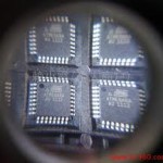
Unlock Microcontroller ATMEGA16A Code
Unlock Microcontroller ATMEGA16A and extract IC Code from its flash and eeprom memory, through focus ion beam technique we can cut off the security fuse bit and remove the protection of MCU;
Unlock Microcontroller ATMEGA16A and extract IC Code from its flash and eeprom memory, through focus ion beam technique we can cut off the security fuse bit and remove the protection of MCU
The Microcontroller ATMEGA16A devices incorporate an on-chip Power-on Reset (POR) circuitry, which provides an internal chip Reset for most power-up situations.
The on-chip POR circuit holds the chip in Reset until VDD has reached a high enough level for proper operation. To take advantage of the internal POR, program the GP3/MCLR/VPP pin as MCLR and tie through a resistor to VDD, or program the pin as GP3.
An internal weak pull-up resistor is implemented using a transistor (refer to Table 12-2 for the pull-up resistor ranges). This will eliminate external RC components usually needed to create a Power-on Reset. A maximum rise time for VDD is specified before crack mcu attiny13a code.
See Section 12.0 “Electrical Characteristics” for details. When the devices start normal operation (exit the Reset condition), device operating parameters (voltage, frequency, temperature,…) must be met to ensure operation.
If these conditions are not met, the devices must be held in Reset until the operating parameters are met. A simplified block diagram of the on-chip Power-on Reset circuit.
The Power-on Reset circuit and the Device Reset Timer (see Section 9.5 “Device Reset Timer (DRT)”) circuit are closely related. On power-up, the Reset latch is set and the DRT is reset. The DRT timer begins counting once it detects MCLR to be high.
After the time-out period, which is typically 18 ms, it will reset the Reset latch and thus end the on-chip Reset signal. A power-up example where MCLR is held low is shown in Figure 9-3. VDD is allowed to rise and stabilize before bringing MCLR high.
The chip will actually come out of Reset TDRT msec after MCLR goes high. In Figure 9-4, the on-chip Power-on Reset feature is being used (MCLR and VDD are tied together or the pin is programmed to be GP3).
The VDD is stable before the Start-up Timer times out and there is no problem in getting a proper Reset. However, Figure 9-5 depicts a problem situation where VDD rises too slowly.
The time between when the DRT senses that MCLR is high and when MCLR and VDD actually reach their full value, is too long. In this situation, when the Start-up Timer times out, VDD has not reached the VDD (min) value and the chip may not function correctly.
For such situations, we recommend that external RC circuits be used to achieve longer POR delay times (Figure 9-4).
Tags: unlock microcontroller binary archive,unlock microcontroller binary code,unlock microcontroller binary content,unlock microcontroller binary data,unlock microcontroller binary eeprom,unlock microcontroller binary file,unlock microcontroller binary firmware,unlock microcontroller binary information,unlock microcontroller binary memory,unlock microcontroller binary program