-
Product Categories
Live Support Chat


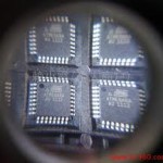
Unlock Microcontroller ATmega1280PV Code
Unlock Microcontroller ATmega1280PV and recover ATmega1280 mcu program code from flash and eeprom, and then copy ATmega1280V microcontroller content to new MCU;

When this bit is set (one), the ADC operates in Free Running mode. In this mode, the ADC samples and updates the data registers continuously. Clearing this bit (zero) will terminate Free Running mode when unlock microcontroller PIC18F66K22 software.
If active channels are used (MUX2 in ADMUX set), the channel must be selected before entering Free Running mode. Selecting an active channel after entering Free Running mode may result in undefined operation from the ADC.
This bit is set (one) when an ADC conversion completes and the data registers are updated. The ADC Conversion Complete Interrupt is executed if the ADIE bit and the I-bit in SREG are set (one). ADIF is cleared by hardware when executing the corresponding interrupt handling vector before unlock microcontroller pic18f85k22 flash.
Alternatively, ADIF is cleared by writing a logical “1” to the flag. Beware that if doing a read-modify-write on ADCSR, a pending interrupt can be disabled. This also applies if the SBI and CBI instructions are used.
When this bit is set (one) and the I-bit in SREG is set (one), the ADC Conversion Complete Interrupt is activated. When an ADC conversion is complete, the result is found in these two registers.
When ADCL is read, the ADC Data Register is not updated until ADCH is read. If the result is left adjusted and no more than 8-bit precision is required, it is sufficient to read ADCH if clone microcontroller pic18f65k90 firmware.
Otherwise, ADCL must be read first, then ADCH. The ADLAR bit in ADMUX affects the way the result is read from the registers. If ADLAR is set, the result is left-adjusted. If ADLAR is cleared (default), the result is right-adjusted.
These bits represent the result from the conversion. For the differential channel, this is the value after gain adjustment, as indicated in Table 20 on page 47. For single-ended conversion, or if ADLAR or SIGN is zero, $000 represents ground and $3FF represents the selected reference voltage minus one LSB.
Tags: unlock microcontroller software archive,unlock microcontroller software binary,unlock microcontroller software code,unlock microcontroller software content,unlock microcontroller software data,unlock microcontroller software eeprom,unlock microcontroller software file,unlock microcontroller software firmware,unlock microcontroller software heximal,unlock microcontroller software information,unlock microcontroller software memory,unlock microcontroller software program