Unlock MCU ATmega169PA Program
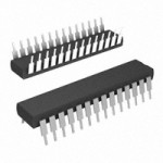
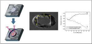
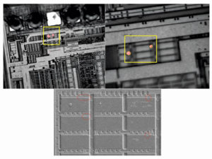
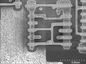
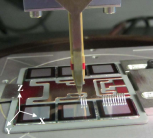
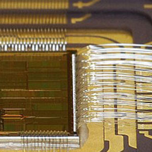
Unlock MCU ATmega169PA Program from microcontroller ATmega169PA flash memory and copy firmware to new MCU, depackage master ATmega169PA mcu by breaking method;
SPI Registers Control and status bits for the Serial Peripheral Interface are contained in registers SPCR (shown in Table 4) and SPSR (shown in Table 5). The SPI data bits are contained in the SPDR register.
Writing the SPI data register during serial data transfer sets the Write Collision bit, WCOL, in the SPSR register. The SPDR is double buffered for writing and the values in SPDR are not changed by Reset when Unlock Microcontroller attiny88 heximal.
Interrupt Registers The global interrupt enable bit and the individual interrupt enable bits are in the IE register. In addition, the individual interrupt enable bit for the SPI is in the SPCR register. Two priorities can be set for each of the six interrupt sources in the IP register.
Dual Data Pointer Registers To facilitate accessing external data memory, two banks of 16 bit Data Pointer Registers are provided: DP0 at SFR address locations 82H-83H and DP1 at 84H-85H. Bit DPS = 0 in SFR WCON selects DP0 and DPS = 1 selects DP1 after Unlock Microcontroller attiny88a hex. The user should always initalize the DPS bit to the appropriate value before accessing the respective Data Pointer register.
Power Off Flag The Power Off Flag (POF) is located at bit_4 (PCON.4) in the PCON SFR. POF is set to “1” during power up. It can be set and reset under software control and is not affected by RESET when Unlock MCU ATmega261A heximal.
The ATMEGA169PA implements 256 bytes of RAM. The upper 128 bytes of RAM occupy a parallel space to the Special Function Registers. That means the upper 128 bytes have the same addresses as the SFR space but are physically separate from SFR space. When an instruction accesses an internal location above address 7FH, the address mode used in the instruction specifies whether the CPU accesses the upper 128 bytes of RAM or the SFR space. Instructions that use direct addressing access SFR space before Unlock MCU atmega164v Program. For example, the following direct addressing instruction accesses the SFR at location 0A0H (which is P2).
Tags: unlock mcu archive,unlock mcu binary,unlock mcu code,unlock mcu content,unlock mcu data,unlock mcu eeprom,unlock mcu file,unlock mcu firmware,unlock mcu heximal,unlock mcu information,unlock mcu memory,unlock mcu program


