-
Product Categories
Live Support Chat


Unlock IC AT89C51ID2 Heximal
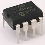
Unlock IC AT89C51ID2 Heximal is a process to break MCU AT89C51ID2 protective system and readout the embedded firmware file from microcontroller at89c51id2 flash memory;
We can Unlock IC AT89C51ID2 Heximal, please view the IC AT89C51ID2 features for your reference:
The Special Function Registers (SFRs) of the AT89C51ID2 fall into the following categories:
C51 core registers: ACC, B, DPH, DPL, PSW, SP
I/O port registers: P0, P1, P2, P3, PI2
Timer registers: T2CON, T2MOD, TCON, TH0, TH1, TH2, TMOD, TL0, TL1, TL2, RCAP2L, RCAP2H Serial I/O port registers: SADDR, SADEN, SBUF, SCON PCA (Programmable Counter Array) registers: CCON, CCAPMx, CL, CH, CCAPxH, CCAPxL (x: 0 to 4) if crack pic18f23k22 IC memory
Power and clock control registers: PCON
Hardware Watchdog Timer registers: WDTRST, WDTPRG
Interrupt system registers: IE0, IPL0, IPH0, IE1, IPL1, IPH1
Keyboard Interface registers: KBE, KBF, KBLS
SPI registers: SPCON, SPSTR, SPDAT 2-wire Interface registers: SSCON, SSCS, SSDAT, SSADR
BRG (Baud Rate Generator) registers: BRL, BDRCON
Flash register: FCON
Clock Prescaler register: CKRL 32 kHz Sub Clock Oscillator registers: CKSEL, OSSCON
Others: AUXR, AUXR1, CKCON0, CKCON1
It is always possible to switch dynamically by software from OscA to OscB, and vice versa by changing CKS bit.
Idle Modes when Unlock IC
Power Down Modes
IDLE modes are achieved by using any instruction that writes into PCON.0 bit (IDL)
IDLE modes A and B depend on previous software sequence, prior to writing into PCON.0 bit:
IDLE MODE A: OscA is running (OscAEn = 1) and selected (CKS = 1) if Unlock IC
IDLE MODE B: OscB is running (OscBEn = 1) and selected (CKS = 0)
The unused oscillator OscA or OscB can be stopped by software by clearing OscAEn or OscBEn respectively.
IDLE mode can be canceled either by Reset, or by activation of any enabled interruption
In both cases, PCON.0 bit (IDL) is cleared by hardware before Unlock IC
Exit from IDLE modes will leave Oscillators control bits (OscEnA, OscEnB, CKS) unchanged.
POWER DOWN modes are achieved by using any instruction that writes into PCON.1 bit (PD)
POWER DOWN modes A and B depend on previous software sequence, prior to writing into PCON.1 bit:
Both OscA and OscB will be stopped.
POWER DOWN mode can be cancelled either by a hardware Reset, an external interruption, or the keyboard interrupt.
By Reset signal: The CPU will restart according to OSC bit in Hardware Security Bit (HSB) register after Unlock IC.
By INT0 or INT1 interruption, if enabled: (standard behavioral), request on Pads must be driven low enough to ensure correct restart of the oscillator which was selected when entering in Power down.
By keyboard Interrupt if enabled: a hardware clear of the PCON.1 flag ensure the restart of the oscillator which was selected when entering in Power down when Unlock IC.
Tags: unlock ic binary archive,unlock ic binary code,unlock ic binary content,unlock ic binary data,unlock ic binary eeprom,unlock ic binary file,unlock ic binary firmware,unlock ic binary information,unlock ic binary memory,unlock ic binary program