-
Product Categories
Live Support Chat


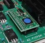
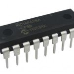
Unlock Chip PIC18F66K80 Software
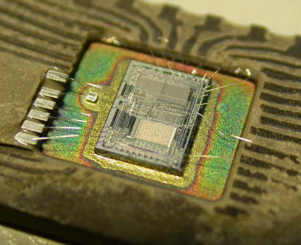
Unlock Chip PIC18F66K80 and extract embedded software from mcu pic18f66k80, locate security fuse bit of microprocessor pic18f66k80 through microcontroller reverse engineering technique;
All of these modes are selected by the user by programming the FOSC<3:0> Configuration bits (CONFIG1H<3:0>). In addition, PIC18F66K80 family devices can switch between different clock sources, either under software control, or under certain conditions, automatically.
This allows for additional power savings by managing device clock speed in real time without resetting the application. The clock sources for the PIC18F66K80 family of devices are shown in Figure 3-1. For the HS and EC mode, there are additional power modes of operation, depending on the frequency of operation if read pic16c621 Chip program.
HS1 is the Medium Power mode with a frequency range of 4 MHz to 16 MHz. HS2 is the High-Power mode, where the oscillator frequency can go from 16 MHz to 25 MHz. HS1 and HS2 are achieved by setting the CONFIG1H<3:0> bits correctly. (For details, see Register 28-2 on page 464.)
EC mode has these modes of operation:
· EC1 – For low power with a frequency range up to 160 kHz
· EC2 – Medium power with a frequency range of 160 kHz to 16 MHz
· EC3 – High power with a frequency range of 16 MHz to 64 MHz after crack pic16f620a Chip bin
EC1, EC2 and EC3 are achieved by setting the CONFIG1H<3:0> correctly. (For details, see Register 28-2 on page 464.) Table 3-1 shows the HS and EC modes’ frequency range and FOSC<3:0> settings. Essentially, PIC18F66K80 family devices have these independent clock sources:
· Primary oscillators
· Secondary oscillators
· Internal oscillator
The primary oscillators can be thought of as the main device oscillators. These are any external oscillators connected to the OSC1 and OSC2 pins, and include the External Crystal and Resonator modes and the External Clock modes. If selected by the FOSC<3:0> Configuration bits (CONFIG1H<3:0>), the internal oscillator block may be considered a primary oscillator.
The internal oscillator block can be one of the following:
· 31 kHz LF-INTOSC source
· 31 kHz to 500 kHz MF-INTOSC source
· 31 kHz to 16 MHz HF-INTOSC source
The particular mode is defined by the FOSC Configuration bits. The details of these modes are covered in Section 3.5 “External Oscillator Modes” .
The secondary oscillators are external clock sources that are not connected to the OSC1 or OSC2 pin. These sources may continue to operate, even after the controller is placed in a power-managed mode. PIC18F66K80 family devices offer the SOSC (Timer1/3/5/7) oscillator as a secondary oscillator source.
The SOSC can be enabled from any peripheral that requests it. The SOSC can be enabled several ways by doing one of the following:
· The SOSC is selected as the source by either of the odd timers, which is done by each respective SOSCEN bit (TxCON<3>)
· The SOSC is selected as the CPU clock source by the SCS bits (OSCCON<1:0>)
· The SOSCGO bit is set (OSCCON2<3>)
The SOSCGO bit is used to warm up the SOSC so that it is ready before any peripheral requests it.
The secondary oscillator has three Run modes. The SOSCSEL<1:0> bits (CONFIG1L<4:3>) decide the SOSC mode of operation:
· 11 = High-Power SOSC Circuit
· 10 = Digital (SCLKI) mode
· 11 = Low-Power SOSC Circuit
If a secondary oscillator is not desired and digital I/O on port pins, RC0 and RC1, is needed, the SOSCSEL bits must be set to Digital mode.
Tags: unlock chip embedded archive,unlock chip embedded code,unlock chip embedded content,unlock chip embedded data,unlock chip embedded eeprom,unlock chip embedded file,unlock chip embedded firmware,unlock chip embedded information,unlock chip embedded memory,unlock chip embedded program