-
Product Categories
Live Support Chat


Unlock Chip PIC18F4520 Firmware
Unlock Chip PIC18F4520 and readout the Firmware from its memory, through focus ion beam technique we can effectively remove the protection of MCU then copy the program and data to other blank Microcontroller;
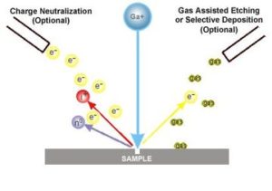
Unlock Chip PIC18F4520 and readout the Firmware from its memory, through focus ion beam technique we can effectively remove the protection of MCU then copy the program and data to other blank Microcontroller
Compensating with the USART
An adjustment may be required when the USART begins to generate framing errors or receives data with errors while in Asynchronous mode. Framing errors indicate that the device clock frequency is too high; to adjust for this, decrement the value in OSCTUNE to reduce the clock frequency. On the other hand, errors in data may suggest that the clock speed is too low; to compensate, increment OSCTUNE to increase the clock frequency.
Compensating with the Timers
This technique compares device clock speed to some reference clock. Two timers may be used; one timer is clocked by the peripheral clock, while the other is clocked by a fixed reference source, such as the Timer1 oscillator.
Both timers are cleared, but the timer clocked by the reference generates interrupts. When an interrupt occurs, the internally clocked timer is read and both timers are cleared. If the internally clocked timer value is greater than expected, then the internal oscillator block is running too fast. To adjust for this, decrement the OSCTUNE register before extract pic16f527 hex.
A CCP module can use free running Timer1 (or Timer3), clocked by the internal oscillator block and an external event with a known period (i.e., AC power frequency). The time of the first event is captured in the CCPRxH:CCPRxL registers and is recorded for use later.
When the second event causes a capture, the time of the first event is subtracted from the time of the second event. Since the period of the external event is known, the time difference between events can be calculated.
If the measured time is much greater than the calculated time, the internal oscillator block is running too fast; to compensate, decrement the OSCTUNE register. If the measured time is much less than the calculated time, the internal oscillator block is running too slow; to compensate, increment the OSCTUNE register when Unlock microcontroller pic16f870.
Like previous PIC18 devices, the PIC18F4520 family includes a feature that allows the device clock source to be switched from the main oscillator to an alternate low-frequency clock source.
PIC18F2420/2520/4420/4520 devices offer two alternate clock sources. When an alternate clock source is enabled, the various power managed operating modes are available.
Essentially, there are three clock sources for these devices:
· Primary oscillators
· Secondary oscillators
· Internal oscillator block
The primary oscillators include the External Crystal and Resonator modes, the External RC modes, the External Clock modes and the internal oscillator block. The particular mode is defined by the FOSC3:FOSC0 configuration bits. The details of these modes are covered earlier in this chapter.The secondary oscillators are those external sources not connected to the OSC1 or OSC2 pins.
These sources may continue to operate even after the controller is placed in a power managed mode. PIC18F4520 devices offer the Timer1 oscillator as a secondary oscillator. This oscillator, in all power managed modes, is often the time base for functions such as a real-time clock which can be applied for IC code extraction.
Most often, a 32.768 kHz watch crystal is connected between the RC0/T1OSO/T13CKI and RC1/T1OSI pins. Like the LP mode oscillator circuit, loading capacitors are also connected from each pin to ground.
The Timer1 oscillator is discussed in greater detail in Section 12.3 “Timer1 Oscillator”.
In addition to being a primary clock source, the internal oscillator block is available as a power managed mode clock source. The INTRC source is also used as the clock source for several special features, such as the WDT and Fail-Safe Clock Monitor.
The clock sources for the PIC18F2420/2520/4420/4520 devices are shown in Figure 2-8. See Section 23.0 “Special Features of the CPU” for Configuration register details.
Tags: उद्धरण देना ic archive,उद्धरण देना microcontroller file,उद्धरण देना इंटीग्रेटेड सर्किट data,उद्धरण देना एमसीयू program,उद्धरण देना टुकड़ा software,तोड़ना ic bin,तोड़ना mcu hex,तोड़ना microcontroller firmware,तोड़ना इंटीग्रेटेड सर्किट flash,तोड़ना एमसीयू eeprom,तोड़ना टुकड़ा code