-
Product Categories
Live Support Chat


Reverse Engineering Microcontroller IC Samsung S3F9454
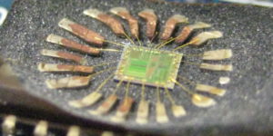
We can Reverse Engineering Microcontroller IC Samsung S3F9454, please chip features below for your reference:
The SAM88RCRI instruction set is designed to support the large register file. It includes a full complement of 8-bit arithmetic and logic operations. There are 41 instructions. No special I/O instructions are necessary because I/O control and data registers are mapped directly into the register file. Flexible instructions for bit addressing, rotate, and shift operations complete the powerful data manipulation capabilities of the SAM88RCRI instruction set.
REGISTER ADDRESSING
To access an individual register, an 8-bit address in the range 0-255 or the 4-bit address of a working register is specified. Paired registers can be used to construct 13-bit program memory or data memory addresses. For detailed information about register addressing, please refer to Chapter 2, “Address Spaces”.
ADDRESSING MODES
There are six addressing modes: Register (R), Indirect Register (IR), Indexed (X), Direct (DA), Relative (RA), and Immediate (IM). For detailed descriptions of these addressing modes, please refer to Chapter 3, “Addressing Modes”.
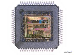
Reverse Engineering Microcontroller IC Samsung S3F9454
FLAG DESCRIPTIONS
The V flag is set to “1” when the result of a two’s-complement operation is greater than + 127 or less than – 128.
It is also cleared to “0” following logic operations.
Following arithmetic, logic, rotate, or shift operations, the sign bit identifies the state of the MSB of the result. A logic zero indicates a positive number and a logic one indicates a negative number when Reverse Engineering Microcontroller IC Samsung S3F9454.
For arithmetic and logic operations, the Z flag is set to “1” if the result of the operation is zero. For operations that test register bits, and for shift and rotate operations, the Z flag is set to “1” if the result is logic zero.
Carry Flag (FLAGS.7, C)
The C flag is set to “1” if the result from an arithmetic operation generates a carry-out from or a borrow to the bit 7 position (MSB). After rotate and shift operations, it contains the last value shifted out of the specified register. Program instructions can set, clear, or complement the carry flag.
Tags: Microcontrolador IC Samsung S3F9454 duplicación,Microcontrolador IC Samsung S3F9454 reelaboración,Microcontrolador IC Samsung S3F9454 replicando,Restauración del microcontrolador IC Samsung S3F9454