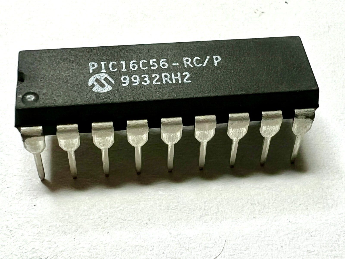
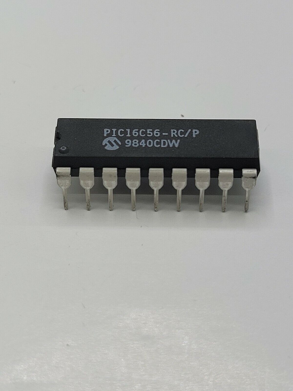
Replicate Microcontroller PIC16C56 Source Code
Replicate microcontroller PIC16C56 source code from secured flash memory and eeprom memory, break the protection over PIC16C56 microprocessor and decrypt microchip MCU PIC16C56 binary data or heximal file;

PORTB is an 8-bit I/O register. Only the low order 6 bits are used (RB5:RB0). Bits 7 and 6 are unimplemented and read as ‘0’s. Please note that RB3 is an input only pin when Reverse Engineering Microcontroller. The configuration word can set several I/O’s to alternate functions for the purpose of Replicate Microcontroller PIC16C56 Source Code.
When acting as alternate functions the pins will read as ‘0’ during port read. Pins RB0, RB1, RB3 and RB4 can be configured with weak pull-ups and also with wake-up on change by Crack AVR Chip Atmel ATtiny12V. The wake-up on change and weak pull-up functions are not pin selectable.
If pin 4 is configured as MCLR, weak pull-up is always off and wake-up on change for this pin is not enabled. PORTC is an 8-bit I/O register. Only the low order 6 bits are used (RC5:RC0). Bits 7 and 6 are unimplemented and read as ‘0’s for the purpose of Unlock microchip MCU PIC16LF526 flash program.
The output driver control register is loaded with the contents of the W register by executing the TRIS f instruction. A ‘1’ from a TRIS register bit puts the corresponding output driver in a hi-impedance mode. A ‘0’ puts the contents of the output data latch on the selected pins, enabling the output buffer to better support the process of Unlock microchip MCU PIC16LF526 flash program. The exceptions are RB3 which is input only and RC5 which may be controlled by the option register.
The equivalent circuit for an I/O port pin is shown in Figure 5-1. All port pins, except RB3 which is input only, may be used for both input and output operations. For input operations these ports are non- latching. Any input must be present until read by an input instruction (e.g., MOVF PORTB,W).
The outputs are latched and remain unchanged until the output latch is rewritten through Clone ST MCU ST7FMC2N7B3 Source Code. To use a port pin as output, the corresponding direction control bit in TRIS must be cleared (= 0). For use as an input, the corresponding TRIS bit must be set. Any I/O pin (except RB3) can be programmed individually as input or output.