-
Product Categories
Live Support Chat


Read Microcontroller PIC16F876 Flash
Cut off the metal wire inside the MCU circuitry layer by focus ion beam and disable the tamper resistance system, Read Microcontroller PIC16F876 Flash and eeprom content direclty out from the memory and copy microcontroller;
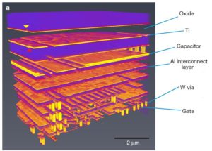
Cut off the metal wire inside the MCU circuitry layer by focus ion beam and disable the tamper resistance system, Read Microcontroller PIC16F876 Flash and eeprom content direclty out from the memory and copy microcontroller
The STATUS register contains the arithmetic status of the ALU, the RESET status and the bank select bits for data memory.
The STATUS register can be the destination for any instruction, as with any other register. If the STATUS register is the destination for an instruction that affects the Z, DC or C bits, then the write to these three bits is disabled.
These bits are set or cleared according to the device logic. Furthermore, the TO and PD bits are not writable, therefore, the result of an instruction with the STATUS register as destination may be different than intended if unlock chip pic16f785 heximal.
For example, CLRF STATUS will clear the upper three bits and set the Z bit. This leaves the STATUS register as 000u u1uu (where u = unchanged). It is recommended, therefore, that only BCF, BSF, SWAPF and MOVWF instructions are used to alter the STATUS register, because these instructions do not affect the Z, C or DC bits from the STATUS register.
For other instructions not affecting any status bits, see the “Instruction Set Summary.”
The OPTION_REG Register is a readable and writable register, which contains various control bits to configure the TMR0 prescaler/WDT postscaler (single assignable register known also as the prescaler), the External INT Interrupt, TMR0 and the weak pull-ups on PORTB when attack chip pic16f913 binary.
The program counter (PC) is 13-bits wide. The low byte comes from the PCL register, which is a readable and writable register. The upper bits (PC<12:8>) are not readable, but are indirectly writable through the PCLATH register. On any RESET, the upper bits of the PC will be cleared. Figure 2-5 shows the two situations for the loading of the PC.
The upper example in the figure shows how the PC is loaded on a write to PCL (PCLATH<4:0> → PCH). The lower example in the figure shows how the PC is loaded during aCALL orGOTO instruction (PCLATH<4:3> → PCH). All PIC16F87X devices are capable of addressing a continuous 8K word block of program memory when crack mcu pic16f916 bin.
The CALL and GOTO instructions provide only 11 bits of address to allow branching within any 2K program memory page. When doing aCALL or GOTO instruction, the upper 2 bits of the address are provided by PCLATH<4:3>. When doing a CALL or GOTO instruction, the user must ensure that the page select bits are programmed so that the desired program memory page is addressed.
If a return from a CALL instruction (or interrupt) is executed, the entire 13-bit PC is popped off the stack. Therefore, manipulation of the PCLATH<4:3> bits is not required for the return instructions (which POPs the address from the stack).
Tags: read microcontroller embedded archive,read microcontroller embedded code,read microcontroller embedded content,read microcontroller embedded data,read microcontroller embedded eeprom,read microcontroller embedded file,read microcontroller embedded firmware,read microcontroller embedded information,read microcontroller embedded memory,read microcontroller embedded program