-
Product Categories
Live Support Chat


Extract Microcontroller PIC16F887 File
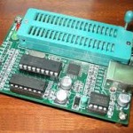
Extract Microcontroller PIC16F887 File out from its memory, normally this file will include the program of flash and data of eeprom, security fuse bit will be cut off after apply the focus ion beam technology over the MCU internal structure which can be discovered by reverse engineering MCU;
Extract Microcontroller PIC16F887 File out from its memory, normally this file will include the program of flash and data of eeprom, security fuse bit will be cut off after apply the focus ion beam technology over the MCU internal structure which can be discovered by reverse engineering MCU
A computed GOTO is accomplished by adding an offset to the program counter (ADDWF PCL). Care should be exercised when jumping into a look-up table or program branch table (computed GOTO) by modifying the PCL register. Assuming that PCLATH is set to the table start address, if the table length is greater than 255 instructions or if the lower 8 bits of the memory address rolls over from 0xFF to 0x00 in the middle of the table, then PCLATH must be incremented for each address rollover that occurs between the table beginning and the target location within the table.
For more information refer to Application Note AN556, “Implementing a Table Read” (DS00556)
There are as many as thirty-five general purpose I/O pins available. Depending on which peripherals are enabled, some or all of the pins may not be available as general purpose I/O. In general, when a peripheral is enabled, the associated pin may not be used as a general purpose I/O pin if Freescale Microprocessor MC9S12XDG128 cracking.
PORTA is a 8-bit wide, bidirectional port. The corresponding data direction register is TRISA (Register 3-2). Setting a TRISA bit (= 1) will make the corresponding PORTA pin an input enabled if Extract Microcontroller, the associated pin may not be used as a general purpose I/O pin. output driver). Clearing a TRISA bit (= 0) will make the corresponding PORTA pin an output (i.e., enables output driver and puts the contents of the output latch on the selected pin). Example 3-1 shows how to initialize PORTA before Pulling motorola Microcontroller MC68HC11A0FN firmware .
Reading the PORTA register (Register 3-1) reads the status of the pins, whereas writing to it will write to the PORT latch. All write operations are read-modify-write address rolls over from 0xFF to 0x00 in the middle of operations. Therefore, a write to a port implies that the port pins are read, this value is modified and then written to the PORT data latch.
The TRISA register (Register 3-2) controls the PORTA pin output drivers, even when they are being used as analog inputs. The user should ensure the bits in the TRISA register are maintained set when using them as analog inputs. I/O pins configured as analog input always read “0”.
Additional Pin Functions
RA0 also has an Ultra Low-Power Wake-up option. The next three sections describe these functions if Extract Microcontroller.
The ANSEL register (Register 3-3) is used to configure the Input mode of an I/O pin to analog. Setting the appropriate ANSEL bit high will cause all digital reads on the pin to be read as ‘0’ and allow analog functions on the pin to operate correctly after Extract Microcontroller.
The state of the ANSEL bits has no affect on digital output functions. A pin with TRIS clear and ANSEL set will still operate as a digital output, but the Input mode will be analog. This can cause unexpected behavior when executing read-modify-write instructions on the affected port after Extract Microcontroller.
Tags: extract microcontroller software archive,extract microcontroller software code,extract microcontroller software content,extract microcontroller software data,extract microcontroller software eeprom,extract microcontroller software file,extract microcontroller software firmware,extract microcontroller software information,extract microcontroller software memory,extract microcontroller software program