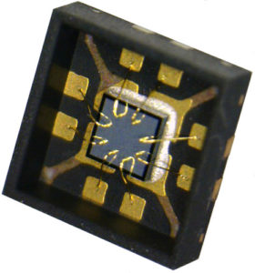
Extract Microchip IC PIC16F690 Code
Extract Microchip IC PIC16F690 Code from MCU’s flash memory, the program can play the exactly the same functions as original Microprocessor PIC16F690, the original MCU breaking will involve security fuse bit disability;

Extract Microchip IC PIC16F690 Code from MCU’s flash memory, the program can play the exactly the same functions as original Microprocessor PIC16F690, the original MCU breaking will involve security fuse bit disability
The Program Counter (PC) is 13 bits wide. The low byte comes from the PCL register, which is a readable and writable register. The high byte (PC<12:8>) is not directly readable or writable and comes from PCLATH. On any Reset, the PC is cleared. Figure 2-9 shows the two situations for the loading of the PC. The upper example in Figure 2-9 shows how the PC is loaded on a write to PCL (PCLATH<4:0> → PCH). The lower example in Figure 2-9 shows how the PC is loaded during aCALL or GOTO instruction (PCLATH<4:3> → PCH).
Executing any instruction with the PCL register as the destination simultaneously causes the Program Counter PC<12:8> bits (PCH) to be replaced by the contents of the PCLATH register. This allows the entire contents of the program counter to be changed by writing the desired upper 5 bits to the PCLATH register. When the lower 8 bits are written to the PCL register, all 13 bits of the program counter will change to the values contained in the PCLATH register and those being written to the PCL register. ospace:none’>Figure 2-9 shows how the PC is loaded during aCALL or GOTO instruction (PCLATH<4:3> → PCH) if Extract Microchip IC.
to the program counter (ADDWF PCL). Care should be exercised when jumping into a look-up table or program branch table (computed GOTO) by modifying the PCL register. Assuming that PCLATH is set to the table start address, if the table length is greater than 255 instructions or if the lower 8 bits of the memory address rolls over from 0xFF to 0x00 in the middle of nd those being written to the PCL register. ospace:none’>Figure 2-9 shows how the PC is loaded during aCALL or GOTO instruction (PCLATH<4:3> → PCH). the table, then PCLATH must be incremented for each address rollover that occurs between the table beginning and the target location within the table. For more information refer to Application Note AN556,
The INDF register is not a physical register. Addressing the INDF register will cause indirect addressing. Indirect addressing is possible by using the INDF register. Any instruction using the INDF register actually instruction (PCLATH<4:3> → PCH).
accesses data pointed to by the File Select Register (FSR). Reading INDF itself indirectly will produce 00h. Writing to the INDF register indirectly results in a no operation (although Status bits may be affected). An effective 9-bit address is obtained by concatenating the 8-bit FSR and the IRP bit of the STATUS register, as shown in Figure 2-10. A simple program to clear RAM location 20h-2Fh using indirect addressing is shown in Example 2-1 -fareast-font-family:宋体;color:black;mso-font-kerning:0pt;mso-ansi-language: EN-US;mso-fareast-language:ZH-CN;mso-bidi-language:AR-SA’>address rolls over from 0xFF to 0x00 in the middle of nd those being written to the PCL register. ospace:none’>Figure 2-9 shows how the PC is loaded during aCALL or GOTO instruction (PCLATH<4:3> → PCH).
Tags: extract microchip ic heximal archive,extract microchip ic heximal code,extract microchip ic heximal content,extract microchip ic heximal data,extract microchip ic heximal eeprom,extract microchip ic heximal file,extract microchip ic heximal firmware,extract microchip ic heximal information,extract microchip ic heximal memory,extract microchip ic heximal program

