-
Product Categories
Live Support Chat


Extract MCU PIC18F1320 Eeprom
Extract MCU PIC18F1320 Eeprom and flash memory firmware to other blank Microcontroller PIC18F1320 and then rewrite the code to blank MCU which will be able to provide the same functions as originals, in order to do that, we need to use nitric accide to dissolve the silicon package of the mcu which is also viewed as IC breaking;
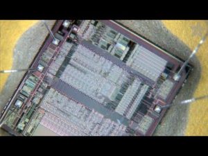
Extract MCU PIC18F1320 Eeprom and flash memory firmware to other blank Microcontroller PIC18F1320 and then rewrite the code to blank MCU which will be able to provide the same functions as originals, in order to do that, we need to use nitric accide to dissolve the silicon package of the mcu
All of the devices in the PIC18F1220/1320 family incorporate a range of features that can significantly reduce power consumption during operation. Key items include:
· Alternate Run Modes: By clocking the controller from the Timer1 source or the internal oscillator block, power consumption during code execution can be reduced by as much as 90%.
· Multiple Idle Modes: The controller can also run with its CPU core disabled, but the peripherals are still active. In these states, power consumption can be reduced even further, to as little as 4% of normal operation requirements.
· On-the-fly Mode Switching: The power managed modes are invoked by user code during operation, allowing the user to incorporate power-saving ideas into their application’s software design.
· Lower Consumption in Key Modules: The power requirements for both Timer1 and the Watchdog Timer have been reduced by up to 80%, with typical values of 1.1 and 2.1 ìA, respectively.
All of the devices in the PIC18F1220/1320 family offer nine different oscillator options, allowing users a wide range of choices in developing application hardware before decrypt microchip pic16f648a.
These include:
· Four Crystal modes, using crystals or ceramic resonators.
· Two External Clock modes, offering the option of using two pins (oscillator input and a divide-by-4 clock output), or one pin (oscillator input, with the second pin reassigned as general I/O).
· Two External RC Oscillator modes, with the same pin options as the External Clock modes.
· An internal oscillator block, which provides an 8 MHz clock (±2% accuracy) and an INTRC source (approximately 31 kHz, stable over temperature and VDD), as well as a range of 6 user-selectable clock frequencies (from 125 kHz to 4 MHz) for a total of 8 clock frequencies.
Besides its availability as a clock source, the internal oscillator block provides a stable reference source that gives the family additional features for robust operation:
· Fail-Safe Clock Monitor: This option constantly monitors the main clock source against a reference signal provided by the internal oscillator. If a clock failure occurs, the controller is switched to the internal oscillator block, allowing for continued low-speed operation, or a safe application shutdown before decipher microchip mcu pic16f874 dump.
· Two-Speed Start-up: This option allows the internal oscillator to serve as the clock source from Power-on Reset, or wake-up from Sleep mode, until the primary clock source is available. This allows for code execution during what would otherwise be the clock start-up interval and can even allow an application to perform routine background activities and return to Sleep without returning to full power operation.
Memory Endurance: The Enhanced Flash cells for both program memory and data EEPROM are rated to last for many thousands of erase/write cycles – up to 100,000 for program memory and 1,000,000 for EEPROM. Data retention without refresh is conservatively estimated to be greater than 40 years.
· Self-programmability: These devices can write to their own program memory spaces under internal software control. By using a bootloader routine located in the protected Boot Block at the top of program memory, it becomes possible to create an application that can update itself in the field.
· Enhanced CCP module: In PWM mode, this module provides 1, 2 or 4 modulated outputs for controlling half-bridge and full-bridge drivers. Other features include auto-shutdown, for disabling PWM outputs on interrupt or other select conditions and auto-restart, to reactivate outputs once the condition has cleared.
· Enhanced USART: This serial communication module features automatic wake-up on Start bit and automatic baud rate detection and supports RS-232, RS-485 and LIN 1.2 protocols, making it ideally suited for use in Local Interconnect Network (LIN) bus applications.
· 10-bit A/D Converter: This module incorporates programmable acquisition time, allowing for a channel to be selected and a conversion to be initiated without waiting for a sampling period and thus, reduce code overhead.
· Extended Watchdog Timer (WDT): This enhanced version incorporates a 16-bit prescaler, allowing a time-out range from 4 ms to over 2 minutes that is stable across operating voltage and temperature.
Tags: extract mcu heximal archive,extract mcu heximal code,extract mcu heximal content,extract mcu heximal data,extract mcu heximal eeprom,extract mcu heximal file,extract mcu heximal firmware,extract mcu heximal information,extract mcu heximal memory,extract mcu heximal program