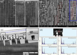
Extract MCU PIC16F676 Code
Extract MCU PIC16F676 Code from its flash memory and eeprom memory, the code will integrate with program and data when recover microprocessor, microcontroller PIC16F676 configuration bits can be dump together after fuse bit being removed by ultra-violet laser;

Extract MCU PIC16F676 Code from its flash memory and eeprom memory, the code will integrate with program and data, microcontroller PIC16F676 configuration bits can be dump together
This document contains device specific information for the PIC16F630/676. Additional information may be found in the PICmicroTM Mid-Range Reference Manual (DS33023), which may be obtained from your local Microchip Sales Representative or downloaded from the Microchip web site. The Reference Manual should be considered a complementary document to this Data Sheet and is highly recommended reading for a better understanding of the device architecture and operation of the peripheral modules.
The PIC16F630 and PIC16F676 devices are covered by this Data Sheet. They are identical, except the PIC16F676 has a 10-bit A/D converter. They come in 14-pin PDIP, SOIC and TSSOP packages. Figure 1-1 shows a block diagram of the PIC16F630/676 devices. Table 1-1 shows the pinout description after Pull PIC 16LF506 MCU firmware out from memory.
PROGRAM MEMORY ORGANIZATION
The PIC16F630/676 devices have a 13-bit program counter capable of addressing an 8K x 14 program memory space. Only the first 1K x 14 (0000h – 03FFh) for the PIC16F630/676 devices is physically implemented. Accessing a location above these boundaries will cause a wrap around within the first 1K x 14 space.
The RESET vector is at 0000h and the interrupt vector is at 0004h.
DATA MEMORY ORGANIZATION
The data memory (see Figure 2-2) is partitioned into two banks, which contain the General Purpose registers and the Special Function registers. The Special Function registers are located in the first 32 locations of each bank. Register locations 20h-5Fh are General Purpose registers, implemented as static RAM and are mapped across both banks. All other RAM is unimplemented and returns ‘0’ when read. RP0 (STATUS<5>) is the bank select bit after Microchip MCU PIC16F73 memory hacking.
SPECIAL FUNCTIONS REGISTERS
The Special Function registers are registers used by the CPU and peripheral functions for controlling the desired operation of the device (see Table 2-1). These registers are static RAM. The special registers can be classified into two sets: core and peripheral. The Special Function registers associated with the “core” are described in this section. Those related to the operation of the peripheral features are described in the section of that peripheral feature.
Tags: extract mcu protect archive,extract mcu protect code,extract mcu protect content,extract mcu protect data,extract mcu protect eeprom,extract mcu protect file,extract mcu protect firmware,extract mcu protect information,extract mcu protect memory,extract mcu protect program

