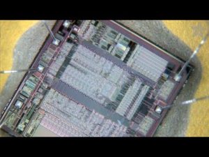
Extract IC PIC18F2331 Firmware
Extract IC PIC18F2331 Firmware from its embedded memory which include flash and eeprom, then replicate the program or data to other blank Microcontroller PIC18F2331 for the exactly cloning.

Extract IC PIC18F2331 Firmware from its embedded memory which include flash and eeprom, then replicate the program or data to other blank Microcontroller PIC18F2331 for the exactly cloning
14-bit Power Control PWM Module:
Up to 4 channels with complementary outputs
Edge- or center-aligned operation
Flexible dead-band generator
Hardware fault protection inputs
Simultaneous update of duty cycle and period:
– Flexible special event trigger output
· Three independent input capture channels:
– Flexible operating modes for period and pulse width measurement
– Special Hall Sensor interface module
– Special event trigger output to other modules
· Quadrature Encoder Interface:
– 2 phase inputs and one index input from encoder
– High and low position tracking with direction status and change of direction interrupt
– Velocity measurement
High-Speed, 200 Ksps 10-bit A/D Converter:
· Up to 9 channels
· Simultaneous two-channel sampling
· Sequential sampling: 1, 2 or 4 selected channels Auto-conversion capability
4-word FIFO with selectable interrupt frequency
Selectable external conversion triggers
Programmable acquisition time
Flexible Oscillator Structure:
· Four crystal modes up to 40 MHz
· Two external clock modes up to 40 MHz
· Internal oscillator block:
– 8 user selectable frequencies: 31 kHz to 8 MHz
– OSCTUNE can compensate for frequency drift
· Secondary oscillator using Timer1 @ 32 kHz
· Fail-Safe Clock Monitor:
– Allows for safe shutdown of device if clock fails
Power-Managed Modes:
Run CPU on, peripherals on
Idle CPU off, peripherals on
Sleep CPU off, peripherals off
Idle mode currents down to 5.8 µA typical
Sleep current down to 0.1 µA typical
Timer1 oscillator, 1.8 µA typical, 32 kHz, 2V
Watchdog Timer (WDT), 2.1 µA typical
Two-Speed oscillator start-up
Peripheral Highlights:
· High current sink/source 25 mA/25 mA
· Three external interrupts
· Two Capture/Compare/PWM (CCP) modules:
– Capture is 16-bit, max. resolution 6.25 ns (TCY/16)
– Compare is 16-bit, max. resolution 100 ns (TCY)
– PWM output: PWM resolution is 1 to 10 bits
· Enhanced USART module:
– Supports RS-485, RS-232 and LIN 1.2
– Auto-Wake-up on Start bit
– Auto-Baud detect
· RS-232 operation using internal oscillator block (no external crystal required)
Tags: извлекать ic bin,извлекать mcu hex,извлекать интегральная схема eeprom,извлекать микроконтроллер firmware,извлекать чип code,отпереть ic flash,отпереть mcu program,отпереть интегральная схема software,отпереть микроконтроллер archive,отпереть чип dump

