Decrypt Chip ATMEGA324A Code
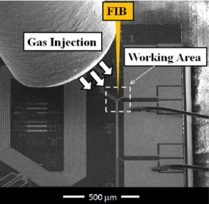
Decrypt Chip ATMEGA324A and remove the tamper resistance system of microcontroller, then extract IC code out from the MCU ATmega324A which can provide the same functions as original MCU ATmega324A.
Decrypt Chip ATMEGA324A and remove the tamper resistance system of microcontroller, then extract IC code out from the MCU ATmega324A which can provide the same functions as original MCU ATmega324A
Note that this oscillator is used to time EEPROM and Flash write accesses, and these write times will be affected accordingly. If the EEPROM or Flash are written, do not calibrate to more than 8.8 MHz. Otherwise, the EEPROM or Flash write may fail.
The CAL7 bit determines the range of operation for the oscillator. Setting this bit to 0 gives the lowest frequency range, setting this bit to 1 gives the highest frequency range. The two frequency ranges are overlapping, in other words a setting of OSCCAL = 0x7F gives a higher frequency than OSCCAL = 0x80 if crack microcontroller pic18f6527 hex.
The CAL6..0 bits are used to tune the frequency within the selected range. A setting of 0x00 gives the lowest frequency in that range, and a setting of 0x7F gives the highest frequency in the range. Incrementing CAL6..0 by 1 will give a frequency increment of less than 2% in the frequency range 7.3 – 8.1 MHz.
The 128 kHz internal Oscillator is a low power Oscillator providing a clock of 128 kHz. The frequency is nominal at 3V and 25°C. This clock may be select as the system clock by programming the CKSEL Fuses to “11” as shown in Table 16 after extract ic pic18f6627 code.
When this clock source is selected, start-up times are determined by the SUT Fuses as shown in Table 17. To drive the device from an external clock source, XTAL1 should be driven as shown in Figure 24. To run the device on an external clock, the CKSEL Fuses must be programmed to “0000”.
When applying an external clock, it is required to avoid sudden changes in the applied clock frequency to ensure stable operation of the MCU. A variation in frequency of more than 2% from one clock cycle to the next can lead to unpredictable behavior. If changes of more than 2% is required, ensure that the MCU is kept in Reset during the changes.
Note that the System Clock Prescaler can be used to implement run-time changes of the internal clock frequency while still ensuring stable operation. Refer to “System Clock Prescaler” on page 48 for details. The device can output the system clock on the CLKO pin. To enable the output, the CKOUT Fuse has to be programmed before extract chip pic18f8622 program.
This mode is suitable when the chip clock is used to drive other circuits on the system. The clock also will be output during reset, and the normal operation of I/O pin will be overridden when the fuse is programmed. Any clock source, including the internal RC Oscillator, can be selected when the clock is output on CLKO. If the System Clock Prescaler is used, it is the divided system clock that is output.
Tags: decrypt chip bin,decrypt chip code,decrypt chip content,decrypt chip data,decrypt chip eeprom,decrypt chip file,decrypt chip firmware,decrypt chip hex,decrypt chip information,decrypt chip memory,decrypt chip program