-
Product Categories
Live Support Chat


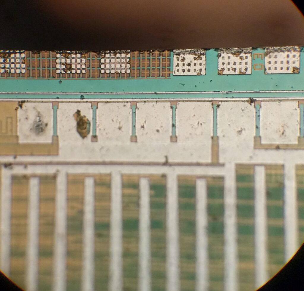
Decipher Microchip MCU PIC16F874 Dump
Decipher Microchip MCU PIC16F874 Dump is a process to recover original code from microcontroller pic16f874 after reading the embedded firmware from locked flash memory of pic16f874;
Peripheral Features:
· Timer0: 8-bit timer/counter with 8-bit prescaler
· Timer1: 16-bit timer/counter with prescaler, can be incremented during SLEEP via external crystal/clock
· Timer2: 8-bit timer/counter with 8-bit period register, prescaler and postscaler when attack avr atmel attiny13
· Two Capture, Compare, PWM modules
– Capture is 16-bit, max. resolution is 12.5 ns
– Compare is 16-bit, max. resolution is 200 ns
– PWM max. resolution is 10-bit
· 10-bit multi-channel Analog-to-Digital converter
· Synchronous Serial Port (SSP) with SPI (Master mode) and I2C (Master/Slave)
· Universal Synchronous Asynchronous Receiver Transmitter (USART/SCI) with 9-bit address detection after decipher Microchip MCU
· Parallel Slave Port (PSP) 8-bits wide, with external RD, WR and CS controls (40/44-pin only)
· Brown-out detection circuitry for Brown-out Reset (BOR)
This document contains device specific information.
Additional information may be found in the PICmicro™ Mid-Range Reference Manual (DS33023), which may be obtained from your local Microchip Sales Representative or downloaded from the Microchip website. The Reference Manual should be considered a complementary document to this data sheet, and is highly recommended reading for a better understanding of the device architecture and operation of the peripheral modules.
Compare is 16-bit, max. resolution is 200 ns
DEVICE OVERVIEW
– PWM max. resolution is 10-bit
· 10-bit multi-channel Analog-to-Digital converter
· Synchronous Serial Port (SSP) with SPI (Master mode) and I2C (Master/Slave)
· Universal Synchronous Asynchronous Receiver Transmitter (USART/SCI) with 9-bit address detection
· Parallel Slave Port (PSP) 8-bits wide, with external RD, WR and CS controls (40/44-pin only)
· Brown-out detection circuitry for Brown-out Reset (BOR)
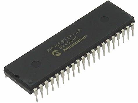
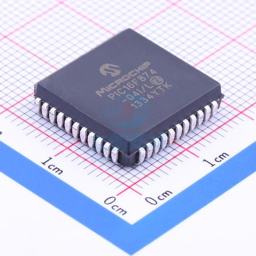
There are four devices (PIC16F873, PIC16F874, PIC16F876 and PIC16F877) covered by this datasheet. The PIC16F876/873 devices come in 28-pin packages and the PIC16F877/874 devices come in 40-pin packages. The Parallel Slave Port is not implemented on the 28-pin devices.
The following device block diagrams are sorted by pin number; 28-pin for Figure 1-1 and 40-pin for Figure 1-2.
The 28-pin and 40-pin pinouts are listed in Table 1-1 and Table 1-2, respectively.
– PWM max. resolution is 10-bit
· 10-bit multi-channel Analog-to-Digital converter
· Synchronous Serial Port (SSP) with SPI (Master mode) and I2C (Master/Slave)
· Universal Synchronous Asynchronous Receiver
Transmitter (USART/SCI) with 9-bit address detection
· Parallel Slave Port (PSP) 8-bits wide, with external RD, WR and CS controls (40/44-pin only)
· Brown-out detection circuitry for Brown-out Reset (BOR)