Crack Microcontroller PIC18F14K22 Heximal
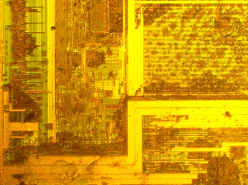
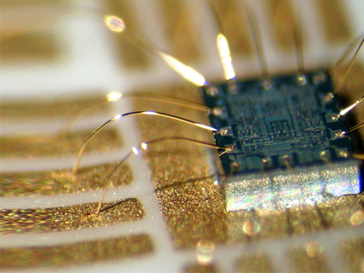
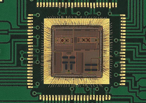
Crack Microcontroller PIC18F14K22 starts from breaking microchip pic18f14k22 flash memory and then readout the secured Heximal from processor pic18f14k22 flash memory;

The Fail-Safe Clock Monitor (FSCM) allows the device to continue operating should the external oscillator fail. The FSCM can detect oscillator failure any time after the Oscillator Start-up Timer (OST) has expired. The FSCM is enabled by setting the FCMEN bit in the CONFIG1H Configuration register. The FSCM is applicable to all external oscillator modes (LP, XT, HS, EC and RC).
The FSCM module detects a failed oscillator by comparing the external oscillator to the FSCM sample clock. The sample clock is generated by dividing the LFINTOSC by 64. See Figure 2-6. Inside the fail detector block is a latch. The external clock sets the latch on each falling edge of the external clock.
The sample clock clears the latch on each rising edge of the sample clock. A failure is detected when an entire half-cycle of the sample clock elapses before the primary clock goes low. When the external clock fails, the FSCM switches the device clock to an internal clock source and sets the bit flag OSCFIF of the PIR2 register before breaking Microcontroller.
The OSCFIF flag will generate an interrupt if the OSCFIE bit of the PIE2 register is also set. The device firmware can then take steps to mitigate the problems that may arise from a failed clock. The system clock will continue to be sourced from the internal clock source until the device firmware successfully restarts the external oscillator and switches back to external operation.
An automatic transition back to the failed clock source will not occur. The internal clock source chosen by the FSCM is determined by the IRCF<2:0> bits of the OSCCON register. This allows the internal oscillator to be configured before a failure occurs if copying Microcontroller binary.
The Fail-Safe condition is cleared by either one of the following:
· Any Reset
· By toggling the SCS1 bit of the OSCCON register
Both of these conditions restart the OST. While the OST is running, the device continues to operate from the INTOSC selected in OSCCON. When the OST times out, the Fail-Safe condition is cleared and the device automatically switches over to the external clock source. The Fail-Safe condition need not be cleared before the OSCFIF flag is cleared.
The FSCM is designed to detect an oscillator failureafter the Oscillator Start-up Timer (OST) has expired. The OST is used after waking up from Sleep and after any type of Reset. The OST is not used with the EC or RC Clock modes so that the FSCM will be active as soon as the Reset or wake-up has completed if decrypt Microcontroller firmware.
When the FSCM is enabled, the Two-Speed Start-up is also enabled. Therefore, the device will always be executing code while the OST is operating. As Harvard architecture devices, the data and program memories use separate busses; this allows for concurrent access of the two memory spaces.
The data EEPROM, for practical purposes, can be regarded as a peripheral device, since it is addressed and accessed through a set of control registers. PIC18 microcontrollers implement a 21-bit program counter, which is capable of addressing a 2-Mbyte Program Memory (PC) space.
Accessing a location between the upper boundary of the physically implemented memory and the 2-Mbyte address will return all ‘0’s (a NOP instruction). This family of devices contain the following:
· PIC18F13K22/LF13K22: 8 Kbytes of Flash Memory, up to 4,096 single-word instructions
· PIC18F14K22/LF14K22: 16 Kbytes of Flash Memory, up to 8,192 single-word instructions
PIC18 devices have two interrupt vectors and one Reset vector. The Reset vector address is at 0000h and the interrupt vector addresses are at 0008h and 0018h.
Tags: crack microcontroller flash archive,crack microcontroller flash code,crack microcontroller flash content,crack microcontroller flash data,crack microcontroller flash eeprom,crack microcontroller flash file,crack microcontroller flash firmware,crack microcontroller flash information,crack microcontroller flash memory,crack microcontroller flash program


