-
Product Categories
Live Support Chat


Crack Microcontroller ATmega16L Heximal
Crack Microcontroller ATmega16L and dump heximal out from MCU ATmega16L memory, by using laser cutting to remove the security fuse and turns the status of Microprocessor into open one, after decapsulate the silicon package of breaking Microcomputer;
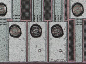
Crack Microcontroller ATmega16L and dump heximal out from MCU ATmega16L memory, by using laser cutting to remove the security fuse and turns the status of Microprocessor into open one, after decapsulate the silicon package of it
The device is manufactured using Atmel’s high density nonvolatile memory technology. The On-chip ISP Flash allows the program memory to be reprogrammed in-system through an SPI serial interface, by a conventional nonvolatile memory programmer, or by an On-chip Boot program running on the AVR core. The boot program can use any interface to download the application program in the Application Flash memory when Crack Microcontroller.
Software in the Boot Flash section will continue to run while the Application Flash section is updated, providing true Read-While-Write operation. By combining an 8-bit RISC CPU with In-System Self-Programmable Flash on a monolithic chip, the Atmel ATmega16 is a powerful microcontroller that provides a highly-flexible and cost-effective solution to many embedded control applications.
The ATmega16 AVR is supported with a full suite of program and system development tools including: C compilers, macro assemblers, program debugger/simulators, in-circuit emulators, and evaluation kits before Pull atmel avr microcontroller program out.
Port A serves as the analog inputs to the A/D Converter. Port A also serves as an 8-bit bi-directional I/O port, if the A/D Converter is not used. Port pins can provide internal pull-up resistors (selected for each bit). The Port A output buffers have symmetrical drive characteristics with both high sink and source capability.
When pins PA0 to PA7 are used as inputs and are externally pulled low, they will source current if the internal pull-up resistors are activated. The Port A pins are tri-stated when a reset condition becomes active, even if the clock is not running.
Port B is an 8-bit bi-directional I/O port with internal pull-up resistors (selected for each bit). The Port B output buffers have symmetrical drive characteristics with both high sink and source capability. As inputs, Port B pins that are externally pulled low will source current if the pull-up resistors are activated.
The Port B pins are tri-stated when a reset condition becomes active, even if the clock is not running. Port C is an 8-bit bi-directional I/O port with internal pull-up resistors (selected for each bit). The Port C output buffers have symmetrical drive characteristics with both high sink and source capability.
As inputs, Port C pins that are externally pulled low will source current if the pull-up resistors are activated. The Port C pins are tri-stated when a reset condition becomes active, even if the clock is not running. If the JTAG interface is enabled, the pull-up resistors on pins PC5(TDI), PC3(TMS) and PC2(TCK) will be activated even if a reset occurs.
Port D is an 8-bit bi-directional I/O port with internal pull-up resistors (selected for each bit). The Port D output buffers have symmetrical drive characteristics with both high sink and source capability. As inputs, Port D pins that are externally pulled low will source current if the pull-up resistors are activated. The Port D pins are tri-stated when a reset condition becomes active, even if the clock is not running.
Tags: crack microcontroller protected archive,crack microcontroller protected code,crack microcontroller protected content,crack microcontroller protected data,crack microcontroller protected eeprom,crack microcontroller protected file,crack microcontroller protected firmware,crack microcontroller protected information,crack microcontroller protected memory,crack microcontroller protected program
