-
Product Categories
Live Support Chat


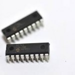
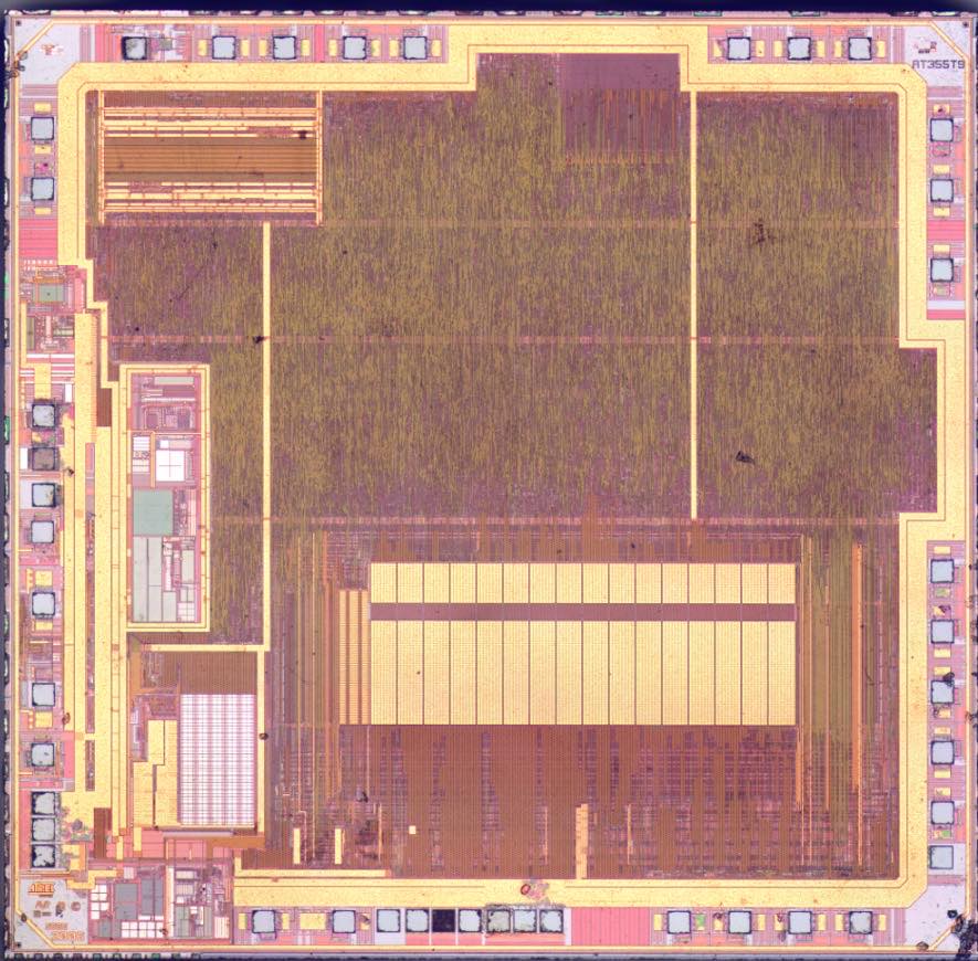
Crack Microchip MCU IC PIC16C54C Firmware
Crack Microchip MCU IC PIC16C54C Firmware and extract the IC code from flash memory, fuse bit of mcu will be broken in order to remove the protection;
12-bit wide instructions when crack PIC MCU
8-bit wide data path
Seven or eight special function hardware registers
Two-level deep hardware stack if crack PIC MCU
Direct, indirect and relative addressing modes for
data and instructions
Peripheral Features:
· 8-bit real time clock/counter (TMR0) with 8-bit
programmable prescaler
· Power-on Reset (POR)
Note:
PIC16C5X refers to all revisions of the part
· Device Reset Timer (DRT)
(i.e., PIC16C54 refers to PIC16C54, PIC16C54A, and PIC16C54C), unless specifically called out otherwise for the purpose of crack PIC MCU.
High-Performance RISC CPU:
· Only 33 single word instructions to learn
· All instructions are single cycle except for program branches which are two-cycle
· Operating speed: DC – 40 MHz clock input DC – 100 ns instruction cycle
· Watchdog Timer (WDT) with its own on-chip RC oscillator for reliable operation
· Programmable Code Protection
· Power saving SLEEP mode
· Selectable oscillator options:
– RC: Low cost RC oscillator
– XT: Standard crystal/resonator when PIC MCU crack
– HS: High speed crystal/resonator
– LP: Power saving, low frequency crystal
CMOS Technology:
· Low power, high speed CMOS EPROM/ROM technology
· Fully static design
· Wide operating voltage and temperature range:
– EPROM Commercial/Industrial 2.0V to 6.25V
– ROM Commercial/Industrial 2.0V to 6.25V
– EPROM Extended 2.5V to 6.0V
– ROM Extended 2.5V to 6.0V
· Low power consumption
– < 2 mA typical @ 5V, 4 MHz
– 15 µA typical @ 3V, 32 kHz
– < 0.6 µA typical standby current
(with WDT disabled) @ 3V, 0°C to 70°C
Note:
In this document, figure and table titles refer to all varieties of the part number indicated, (i.e., The title “Figure 15-1: Load
Conditions For Device Timing Specifications – PIC16C54A”, also refers to PIC16LC54A and PIC16LV54A parts),
Tags: crack pic mcu binary file,crack pic mcu dump information,crack pic mcu embedded firmware,crack pic mcu encrypt program,crack pic mcu flash content,crack pic mcu heximal data,crack pic mcu locked archive,crack pic mcu protect eeprom,crack pic mcu software memory,crack pic mcu source code