Crack MCU PIC18F43K22 Eeprom
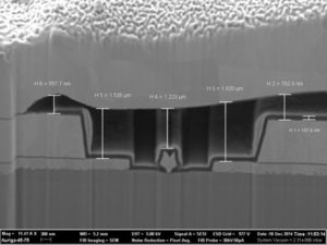
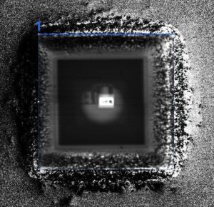
Crack MCU PIC18F43K22 Eeprom starts from disable the security fuse and reset the status of Microcontroller from locked to unlocked, then the firmware will be read out directly;
The oscillator module has a wide variety of clock sources and selection features that allow it to be used in a wide range of applications while maximizing performance and minimizing power consumption. Figure 2-1 illustrates a block diagram of the oscillator module.
Crack MCU PIC18F43K22 Eeprom
Clock sources can be configured from external oscillators, quartz crystal resonators, ceramic resonators and Resistor-Capacitor (RC) circuits. In addition, the system clock source can be configured from one of three internal oscillators, with a choice of speeds selectable via software. Additional clock features include:
· Selectable system clock source between external or internal sources via software
· Two-Speed Start-up mode, which minimizes latency between external oscillator start-up and code execution.
· Fail-Safe Clock Monitor (FSCM) designed to detect a failure of the external clock source (LP, XT, HS, EC or RC modes) and switch automatically to the internal oscillator.
· Oscillator Start-up Timer (OST) ensures stability of crystal oscillator sources.
The primary clock module can be configured to provide one of six clock sources as the primary clock. The HS and EC oscillator circuits can be optimized for power consumption and oscillator speed using settings in FOSC to crack IC PIC18F2221 Firmware<3:0>. Additional FOSC<3:0> selections enable RA6 to be used as I/O or CLKO (FOSC/4) for RC, EC and INTOSC Oscillator modes.
Primary Clock modes are selectable by the FOSC<3:0> bits of the CONFIG1H Configuration register. The primary clock operation is further defined by these Configuration and register bits:
The OSCCON, OSCCON2 and OSCTUNE registers (Register 2-1 to Register 2-3) control several aspects of the device clock’s operation, both in full-power operation and in power-managed modes.
· Main System Clock Selection (SCS)
· Primary Oscillator Circuit Shutdown (PRISD)
· Secondary Oscillator Enable (SOSCGO)
· Primary Clock Frequency 4x multiplier (PLLEN)
· Internal Frequency selection bits (IRCF, INTSRC)
· Clock Status bits (OSTS, HFIOFS, MFIOFS, LFIOFS. SOSCRUN, PLLRDY)
· Power management selection (IDLEN)
The System Clock Select bits, SCS<1:0>, select the main clock source. The available clock sources are
· Primary clock defined by the FOSC<3:0> bits of CONFIG1H. The primary clock can be the primary oscillator, an external clock, or the internal oscillator block.
· Secondary clock (secondary oscillator)
· Internal oscillator block (HFINTOSC, MFINTOSC and LFINTOSC).
The clock source changes immediately after one or more of the bits is written to, following a brief clock transition interval. The SCS bits are cleared to select the primary clock on all forms of Reset. The Internal Oscillator Frequency Select bits (IRCF<2:0>) select the frequency output of the internal oscillator block. The choices are the LFINTOSC source (31.25 kHz), the MFINTOSC source (31.25 kHz, 250 kHz or 500 kHz) and the HFINTOSC source (16 MHz) or one of the frequencies derived from the HFINTOSC postscaler (31.25 kHz to 8 MHz).
If the internal oscillator block is supplying the main clock, changing the states of these bits will have an immediate change on the internal oscillator’s output. On device Resets, the output frequency of the internal oscillator is set to the default frequency of 1 MHz. When a nominal output frequency of 31.25 kHz is selected (IRCF<2:0> = 000), users may choose which internal oscillator acts as the source. This is done with the INTSRC bit of the OSCTUNE register and MFIOSEL bit of the OSCCON2 register.
This option allows users to select a 31.25 kHz clock (MFINTOSC or HFINTOSC) that can be tuned using the TUN<5:0> bits in OSCTUNE register, while maintaining power savings with a very low clock speed. LFINTOSC always remains the clock source for features such as the Watchdog Timer and the Fail-Safe Clock Monitor, regardless of the setting of INTSRC and MFIOSEL bits This option allows users to select the tunable and more precise HFINTOSC as a clock source, while maintaining power savings with a very low clock speed.
The IDLEN bit of the OSCCON register determines whether the device goes into Sleep mode or one of the Idle modes when the SLEEP instruction is executed. Clock Source modes can be classified as external or internal.
· External Clock modes rely on external circuitry for the clock source. Examples are: Clock modules (EC mode), quartz crystal resonators or ceramic resonators (LP, XT and HS modes) and Resistor-Capacitor (RC mode) circuits.
· Internal clock sources are contained internally within the Oscillator block. The Oscillator block has three internal oscillators: the 16 MHz High-Frequency Internal Oscillator (HFINTOSC), 500 kHz Medium-Frequency Internal Oscillator (MFINTOSC) and the 31.25 kHz Low-Frequency Internal Oscillator (LFINTOSC).
The system clock can be selected between external or internal clock sources via the System Clock Select (SCS<1:0>) bits of the OSCCON register. When the oscillator module is configured for LP, XT or HS modes, the Oscillator Start-up Timer (OST) counts 1024 oscillations from OSC1.
Tags: crack mcu heximal archive,crack mcu heximal code,crack mcu heximal content,crack mcu heximal data,crack mcu heximal eeprom,crack mcu heximal file,crack mcu heximal firmware,crack mcu heximal information,crack mcu heximal memory,crack mcu heximal program


