-
Product Categories
Live Support Chat


Crack MCU PIC16F916 Binary
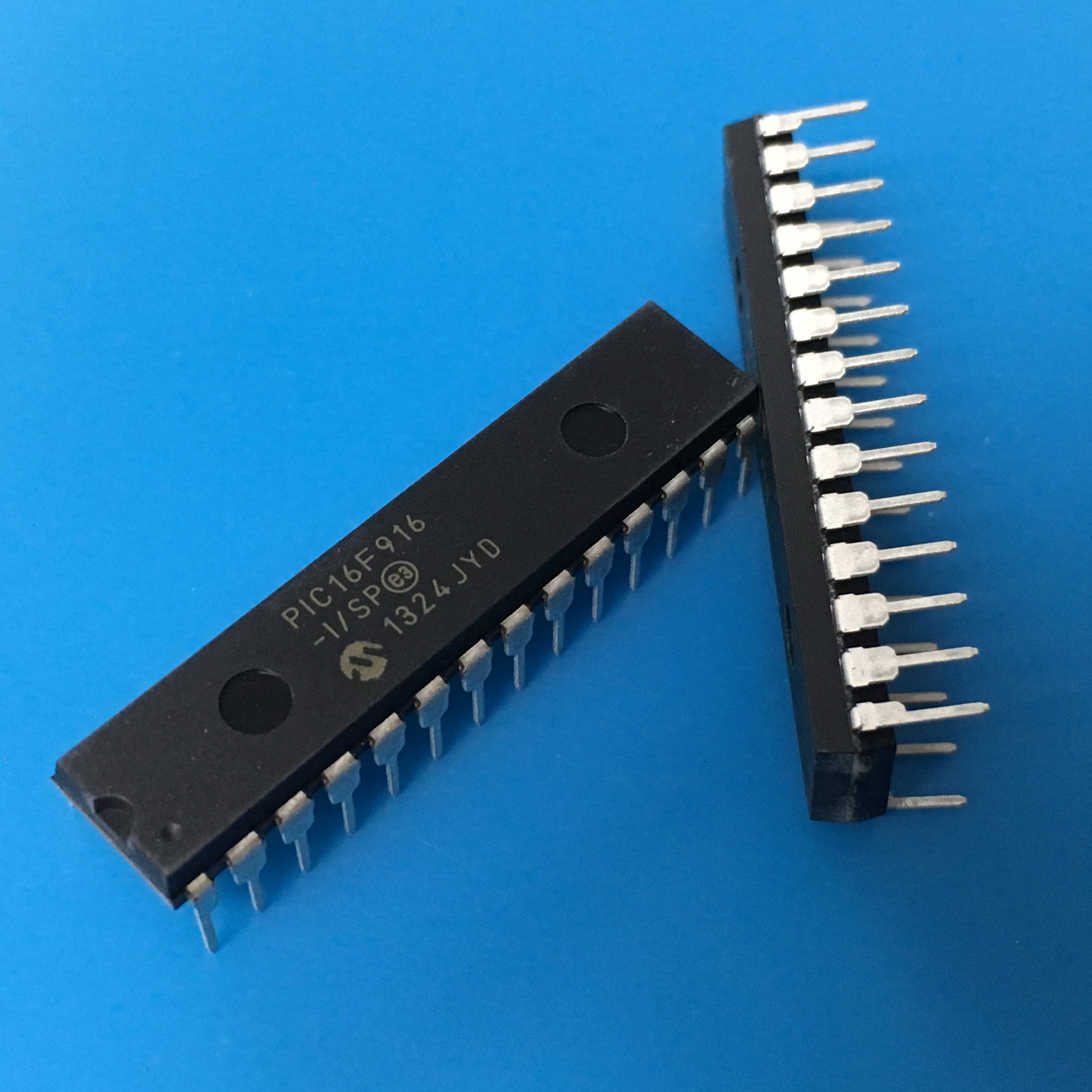
Crack MCU PIC16F916 and copy microcontroller pic16f916 Binary from flash and eeprom memory, the pic16f916 locked memory reading need to reset the status of microprocessor;
DEVICE OVERVIEW
The PIC16F91X/946 devices are covered by this datasheet. They are available in 28/40/44/64-pin packages. Figure 1-1 shows a block diagram of the PIC16F913/916 device, Figure 1-2 shows a block diagram of the PIC16F914/917 device, and Figure 1-3 shows a block diagram of the PIC16F946 device. Table 1-1 shows the pinout descriptions.
MEMORY ORGANIZATION
The PIC16F91X/946 has a 13-bit program counter capable of addressing a 4K x 14 program memory space for the PIC16F913/914 (0000h-0FFFh) and an 8K x 14 program memory space for the PIC16F916 and PIC16F946 (0000h-1FFFh). Accessing a location above the memory boundaries for the PIC16F913 and PIC16F914 will cause a wrap around within the first 4K x 14 space. The Reset vector is at 0000h and the interrupt vector is at 0004h after Crack pic16f873 MCU.
DATA MEMORY ORGANIZATION
Each bank extends up to 7Fh (128 bytes). The lower locations of each bank are reserved for the Special Function Registers. Above the Special Function Registers are the General Purpose Registers, implemented as static RAM. All implemented banks contain Special Function Registers. Some frequently used Special Function Registers from one bank are mirrored in another bank for code reduction and quicker access.
The Special Function Registers are registers used by the CPU and peripheral functions for controlling the desired operation of the device (see Tables 2-1, 2-2, 2-3 and 2-4). These registers are static RAM after attack atmega64L MCU.
The Special Function Registers can be classified into two sets: core and peripheral. The Special Function Registers associated with the “core” are described in this section. Those related to the operation of the peripheral features are described in the section of that peripheral feature.