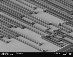
Crack MCU ATtiny13V Heximal
Crack MCU ATtiny13V and recover Heximal from microcontroller ATtiny13V flash memory, copy program/code to blank Microprocessor for an exactly Microcontroller cloning;
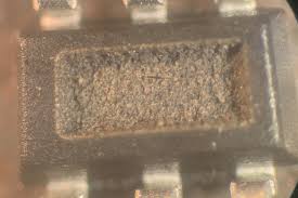
Crack MCU ATtiny13V and recover Heximal from microcontroller ATtiny13V flash memory, copy programcode to blank Microprocessor for an exactly Microcontroller cloning
Wrong values read after Erase Only operation
At supply voltages below 2.7 V, an EEPROM location that is erased by the Erase Only operation may read as programmed (0x00).
Problem Fix/Workaround
If it is necessary to read an EEPROM location after Erase Only, use an Atomic Write operation with 0xFF as data in order to erase a location. In any case, the Write Only operation can be used as intended. Thus no special considerations are needed as long as the erased location is not read before it is programmed when Crack Microcontroller PIC18F23K22 memory.
High Voltage Serial Programming Flash, EEPROM, Fuse and Lock Bits may fail
Writing to any of these locations and bits may in some occasions fail if Crack MCU.
Problem Fix/Workaround
After a writing has been initiated, always observe the RDY/BSY signal. If the writing should fail, rewrite until the RDY/BSY verifies a correct writing. This will be fixed in revision D before Crack chip PIC18F24K22 heximal.
Device may lock for further programming
Special combinations of fuse bits will lock the device for further programming effectively turning it into an OTP device. The following combinations of settings/fuse bits will cause this effect:
128 kHz internal oscillator (CKSEL[1..0] = 11), shortest start-up time (SUT[1..0] = 00), Debugwire enabled (DWEN = 0) or Reset disabled RSTDISBL = 0.
9.6 MHz internal oscillator (CKSEL[1..0] = 10), shortest start-up time (SUT[1..0] = 00), Debugwire enabled (DWEN = 0) or Reset disabled RSTDISBL = 0.
4.8 MHz internal oscillator (CKSEL[1..0] = 01), shortest start-up time (SUT[1..0] = 00), Debugwire enabled (DWEN = 0) or Reset disabled RSTDISBL = 0.
Problem fix/ Workaround
Avoid the above fuse combinations. Selecting longer start-up time will eliminate the problem.
debugWIRE communication not blocked by lock-bits
When debugWIRE on-chip debug is enabled (DWEN = 0), the contents of program memory and EEPROM data memory can be read even if the lock-bits are set to block further reading of the device.
Problem fix/ Workaround
Do not ship products with on-chip debug of the tiny13 enabled.
Watchdog Timer Interrupt disabled
If the watchdog timer interrupt flag is not cleared before a new timeout occurs, the watchdog will be disabled, and the interrupt flag will automatically be cleared. This is only applicable in interrupt only mode. If the Watchdog is configured to reset the device in the watchdog time-out following an interrupt, the device works correctly.
Problem fix / Workaround
Make sure there is enough time to always service the first timeout event before a new watchdog timeout occurs. This is done by selecting a long enough time-out period.
EEPROM can not be written below 1.9 Volt
Writing the EEPROM at VCC below 1.9 volts might fail.
Problem Fix/Workaround
Do not write the EEPROM when VCC is below 1.9 volts.
Tags: crack mcu protected archive,crack mcu protected code,crack mcu protected content,crack mcu protected data,crack mcu protected eeprom,crack mcu protected file,crack mcu protected firmware,crack mcu protected information,crack mcu protected memory,crack mcu protected program


