Crack MCU ATMEGA8PA Binary
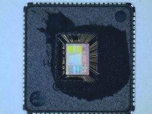
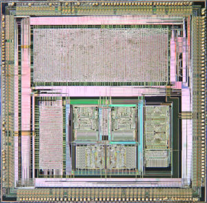
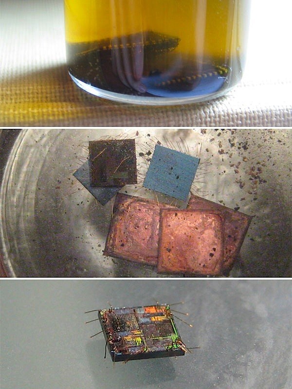
Crack MCU ATMEGA8PA and copy the microcontroller embedded Binary from its flash and eeprom memory to blank Microcontroller ATmega8PA which will act as the original MCU.
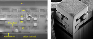
Crack MCU ATMEGA8PA and copy the embedded Binary from its flash and eeprom memory to blank Microcontroller ATmega8PA which will act as the original MCU
The ATMEGA8PA devices are offered with Internal Oscillator mode only when crack MCU ATMEGA8PA.
· INTOSC: Internal 4 MHz Oscillator
The internal oscillator provides a 4 MHz (nominal) system clock (see Section 12.0 “Electrical Characteristics” for information on variation over voltage and temperature).
In addition, a calibration instruction is programmed into the last address of memory, which contains the calibration value for the internal oscillator.
This location is always uncode protected, regardless of the code-protect settings. This value is programmed as a MOVLW xx instruction where xx is the calibration value and is placed at the Reset vector if decode microcontroller winbond W77E058A40DL.
This will load the W register with the calibration value upon Reset and the PC will then roll over to the users program at address 0x000.
The user then has the option of writing the value to the OSCCAL Register (05h) or ignoring it. OSCCAL, when written to with the calibration value, will “trim” the internal oscillator to remove process variation from the oscillator frequency.
The device differentiates between various kinds of Reset:
· Power-on Reset (POR)
· MCLR Reset during normal operation
· MCLR Reset during Sleep when hack microcontroller TEXAS INSTRUMENT MSP430F448
· WDT time-out Reset during normal operation
· WDT time-out Reset during Sleep
Wake-up from Sleep on pin change
Wake-up from Sleep on comparator change
Some registers are not reset in any way, they are unknown on POR and unchanged in any other Reset.
Most other registers are reset to “Reset state” on Power-on Reset (POR), MCLR, WDT or Wake-up on pin change Reset during normal operation. They are not affected by a WDT Reset during Sleep or MCLR Reset during Sleep, since these Resets are viewed as resumption of normal operation.
The exceptions to this are TO, PD, GPWUF and CWUF bits. They are set or cleared differently in different Reset situations. These bits are used in software to determine the nature of Reset.
See Table 9-1 for a full description of Reset states of all registers.
Tags: crack mcu binary archive,crack mcu binary code,crack mcu binary content,crack mcu binary data,crack mcu binary eeprom,crack mcu binary file,crack mcu binary firmware,crack mcu binary information,crack mcu binary memory,crack mcu binary program


