Crack MCU ATmega2561 Heximal
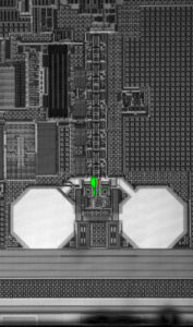
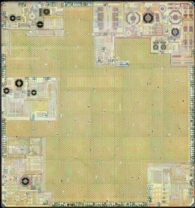
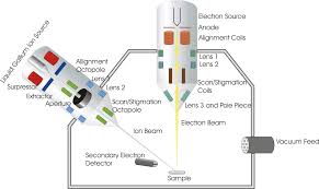
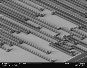
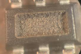
Crack MCU ATmega2561 need to decapsulate the silicon package of Microcontroller and extract the heximal out from its memory which include flash and eeprom;
Crack MCU ATmega2561 need to decapsulate the silicon package of Microcontroller and extract the heximal out from its memory which include flash and eeprom
This documentation contains simple code examples that briefly show how to use various parts of the device. These code examples assume that the part specific header file is included before compilation.
Be aware that not all C compiler vendors include bit definitions in the header files and interrupt handling in C is compiler dependent.
Please confirm with the C compiler documentation for more details. For I/O Registers located in extended I/O map, “IN”, “OUT”, “SBIS”, “SBIC”, “CBI”, and “SBI” instructions must be replaced with instructions that allow access to extended I/O. Typically “LDS” and “STS” combined with “SBRS”, “SBRC”, “SBR”, and “CBR”.
The Atmel® QTouch® Library provides a simple to use solution to realize touch sensitive interfaces on most Atmel AVR® microcontrollers. The QTouch Library includes support for the Atmel QTouch and Atmel QMatrix® acquisition methods.
Touch sensing can be added to any application by linking the appropriate Atmel QTouch Library for the AVR Microcontroller. This is done by using a simple set of APIs to define the touch channels and sensors, and then calling the touch sensing API’s to retrieve the channel information and determine the touch sensor states to facilitate the process of IC memory breaking.
The QTouch Library is FREE and downloadable from the Atmel website at the following location: www.atmel.com/qtouchlibrary. For implementation details and other information, refer to the Atmel QTouch Library User Guide – also available for download from Atmel website.
1. For compatibility with future devices, reserved bits should be written to zero if accessed. Reserved I/O memory addresses should never be written.
2. I/O Registers within the address range 0x00 – 0x1F are directly bit-accessible using the SBI and CBI instructions. In these registers, the value of single bits can be checked by using the SBIS and SBIC instructions.
3. Some of the Status Flags are cleared by writing a logical one to them. Note that, unlike most other AVRs, the CBI and SBI instructions will only operate on the specified bit, and can therefore be used on registers containing such Status Flags.
The CBI and SBI instructions work with registers 0x00 to 0x1F only.
4. When using the I/O specific commands IN and OUT, the I/O addresses 0x00 – 0x3F must be used. When addressing I/O Registers as data space using LD and ST instructions, 0x20 must be added to these addresses.
The ATMEGA2561 is a complex microcontroller with more peripheral units than can be supported within the 64 location reserved in Opcode for the IN and OUT instructions.
For the Extended I/O space from 0x60 – 0xFF in SRAM, only the ST/STS/STD and LD/LDS/LDD instructions can be used.
5. Only valid for ATmega2561.
6. BODS and BODSE only available for picoPower devices ATmega2561
Tags: crack mcu protected archive,crack mcu protected binary,crack mcu protected code,crack mcu protected content,crack mcu protected data,crack mcu protected eeprom,crack mcu protected file,crack mcu protected firmware,crack mcu protected heximal,crack mcu protected information,crack mcu protected memory,crack mcu protected program


