-
Product Categories
Live Support Chat


Crack MCU ATmega1284PV Heximal
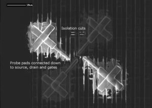
Crack MCU ATmega1284PV Heximal from embedded memory which include the flash and eeprom, then copy the firmware from original Microcontroller to blank MCU to perform the same function:
These bits select the voltage reference for the ADC, as shown in Table 19. If these bits are changed during a conversion, the change will not go into effect until this conversion is complete (ADIF in ADCSR is set).
Whenever these bits are changed, the next conversion will take 25 ADC clock cycles. If active channels are used, using AVCC or an external AREF higher than (AVCC – 1V) is not recommended, as this will affect ADC accuracy.
Crack MCU ATmega1284PV Heximal
The internal voltage reference options may not be used if an external reference voltage is being applied to the AREF pin. The ADLAR bit affects the presentation of the ADC conversion result in the ADC Data Register.
If ADLAR is cleared, the result is right-adjusted. If ADLAR is set, the result is left-adjusted. Changing the ADLAR bit will affect the ADC Data Register immediately, regardless of any ongoing conversions.
For a complete description of this bit, see “The ADC Data Register. The value of these bits selects which analog input is connected to the ADC. In case of differential input (PB3 – PB4), gain selection is also made with these bits. Selecting PB3 as both inputs to the differential gain stage enables offset measurements.
Refer to Table 20 for details. If these bits are changed during a conversion, the change will not go into effect until this conversion is complete (ADIF in ADCSR is set). Writing a logical “1” to this bit enables the ADC. By clearing this bit to zero, the ADC is turned off.
Turning the ADC off while a conversion is in progress will terminate this conversion. In Single Conversion mode, a logical “1” must be written to this bit to start each conversion. In Free Running mode, a logical “1” must be written to this bit to start the first conversion.
When the conversion completes, ADSC returns to zero in Single Conversion mode and stays high in Free Running mode. Writing a “0” to this bit has no effect. When this bit is set (one), the ADC operates in Free Running mode. In this mode, the ADC samples and updates the data registers continuously.
Clearing this bit (zero) will terminate Free Running mode. If active channels are used (MUX2 in ADMUX set), the channel must be selected before entering Free Running mode. Selecting an active channel after entering Free Running mode may result in undefined operation from the ADC.
Tags: crack mcu locked archive,crack mcu locked binary,crack mcu locked code,crack mcu locked content,crack mcu locked data,crack mcu locked eeprom,crack mcu locked file,crack mcu locked firmware,crack mcu locked heximal,crack mcu locked information,crack mcu locked memory,crack mcu locked program