-
Product Categories
Live Support Chat


Crack MCU ATmega1280 Eeprom
Crack MCU ATmega1280 Eeprom and flash memory need to decapsulate the silicon package of the Microcontroller and use microprobe to get access to the databus of the memory of Microcontroller ATmega1280, then extract the code out from MCU ATmega1280;
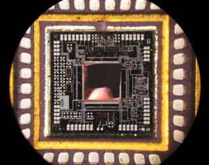
Crack MCU ATmega1280 Eeprom and flash memory need to decapsulate the silicon package of the Microcontroller and use microprobe to get access to the databus of the memory of Microcontroller ATmega1280, then extract the code out from MCU ATmega1280
Port B is an 8-bit bi-directional I/O port with internal pull-up resistors (selected for each bit). The Port B output buffers have symmetrical drive characteristics with both high sink and source capability.
As inputs, Port B pins that are externally pulled low will source current if the pull-up resistors are activated. The Port B pins are tri-stated when a reset condition becomes active, even if the clock is not running. Depending on the clock selection fuse settings which can be used for security fuse removing on microcontroller program copying, PB6 can be used as input to the inverting Oscillator amplifier and input to the internal clock operating circuit.
Depending on the clock selection fuse settings, PB7 can be used as output from the inverting Oscillator amplifier. If the Internal Calibrated RC Oscillator is used as chip clock source, PB7…6 is used as TOSC2…1 input for the Asynchronous Timer/Counter2 if the AS2 bit in ASSR is set.
Port C is a 7-bit bi-directional I/O port with internal pull-up resistors (selected for each bit). The PC5…0 output buffers have symmetrical drive characteristics with both high sink and source capability.
As inputs, Port C pins that are externally pulled low will source current if the pull-up resistors are activated. The Port C pins are tri-stated when a reset condition becomes active, even if the clock is not running.
If the RSTDISBL Fuse is programmed, PC6 is used as an I/O pin. Note that the electrical characteristics of PC6 differ from those of the other pins of Port C.
If the RSTDISBL Fuse is unprogrammed, PC6 is used as a Reset input. A low level on this pin for longer than the minimum pulse length will generate a Reset, even if the clock is not running. The minimum pulse length is given in Table 28-12 on page 323. Shorter pulses are not guaranteed to generate a Reset.
Tags: crack mcu encrypted archive,crack mcu encrypted binary,crack mcu encrypted code,crack mcu encrypted content,crack mcu encrypted data,crack mcu encrypted eeprom,crack mcu encrypted file,crack mcu encrypted firmware,crack mcu encrypted heximal,crack mcu encrypted information,crack mcu encrypted memory,crack mcu encrypted program


