Crack IC dsPIC30F6010 Binary
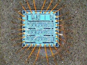
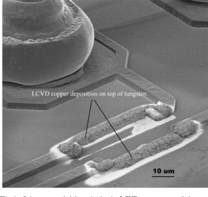
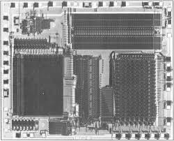
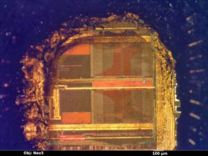
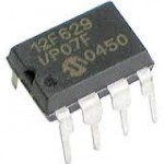
Crack IC dsPIC30F6010 Binary means the firmware will be readout from unlocked microcontroller dsPIC30F6010 and copy the code intot blank MCU for the cloning purpose;
High-Performance Modified RISC CPU:
· Modified Harvard architecture
· C compiler optimized instruction set architecture with flexible Addressing modes
· 84 base instructions
· 24-bit wide instructions, 16-bit wide data path
· 144 Kbytes on-chip Flash program space (Instruction words)
· 8 Kbytes of on-chip data RAM
· 4 Kbytes of non-volatile data EEPROM
· Up to 30 MIPs operation:
– DC to 40 MHz external clock input
– 4 MHz-10 MHz oscillator input with PLL active (4x, 8x, 16x)
· 44 interrupt sources
– 5 external interrupt sources
– 8 user selectable priority levels for each interrupt source
– 4 processor trap sources
· 16 x 16-bit working register array
DSP Engine Features:
· Dual data fetch
· Accumulator write back for DSP operations
· Modulo and Bit-Reversed Addressing modes
· Two, 40-bit wide accumulators with optional saturation logic
· 17-bit x 17-bit single cycle hardware fractional/integer multiplier
· All DSP instructions single cycle
· ± 16-bit single cycle shift
Peripheral Features:
· High current sink/source I/O pins: 25 mA/25 mA
· Timer module with programmable prescaler:
– Five 16-bit timers/counters; optionally pair 16-bit timers into 32-bit timer modules
· 16-bit Capture input functions
· 16-bit Compare/PWM output functions
· 3-wire SPITM modules (supports 4 Frame modes)
· I2CTM module supports Multi-Master/Slave mode and 7-bit/10-bit addressing
· 2 UART modules with FIFO Buffers
· 2 CAN modules, 2.0B compliant
Motor Control PWM Module Features:
· 8 PWM output channels
– Complementary or Independent Output modes
– Edge and Center Aligned modes
· 4 duty cycle generators
· Dedicated time base
· Programmable output polarity
· Dead Time control for Complementary mode
· Manual output control
· Trigger for A/D conversions
Quadrature Encoder Interface Module Analog Features:
· 10-bit Analog-to-Digital Converter (A/D) with 4 S/H Inputs:
– 500 Ksps conversion rate
– 16 input channels
– Conversion available during Sleep and Idle
· Programmable Low Voltage Detection (PLVD)
· Programmable Brown-out Detection and Reset generation
Special Microcontroller Features:
· Enhanced Flash program memory:
– 10,000 erase/write cycle (min.) for industrial temperature range, 100K (typical)
– 100,000 erase/write cycle (min.) for industrial temperature range, 1M (typical)
· Self-reprogrammable under software control
· Power-on Reset (POR), Power-up Timer (PWRT) and Oscillator Start-up Timer (OST)
· Flexible Watchdog Timer (WDT) with on-chip low power RC oscillator for reliable operation
· Fail-Safe clock monitor operation detects clock failure and switches to on-chip low power RC oscillator
· Programmable code protection
· In-Circuit Serial Programming™ (ICSP™)
· Selectable Power Management modes
– Sleep, Idle and Alternate Clock modes
A DSP engine has been included to significantly enhance the core arithmetic capability and throughput.
It features a high speed 17-bit by 17-bit multiplier, a 40-bit ALU, two 40-bit saturating accumulators and a 40-bit bi-directional barrel shifter. Data in the accumulator or any working register can be shifted up to 16 bits right or 16 bits left in a single cycle. The DSP instructions operate seamlessly with all other instructions and have been designed for optimal real-time performance.
The MAC class of instructions can concurrently fetch two data operands from memory, while multiplying two W registers. To enable this concurrent fetching of data operands, the data space has been split for these instructions and linear for all others. This has been achieved in a transparent and flexible manner, by dedicating certain working registers to each address space for the MAC class of instructions.
The core does not support a multi-stage instruction pipeline. However, a single stage instruction pre-fetch mechanism is used, which accesses and partially decodes instructions a cycle ahead of execution, in order to maximize available execution time. Most instructions execute in a single cycle, with certain exceptions.
Tags: crack ic heximal archive,crack ic heximal code,crack ic heximal content,crack ic heximal data,crack ic heximal eeprom,crack ic heximal file,crack ic heximal firmware,crack ic heximal information,crack ic heximal memory,crack ic heximal program


