-
Product Categories
Live Support Chat


Crack Chip dsPIC30F6012 Heximal
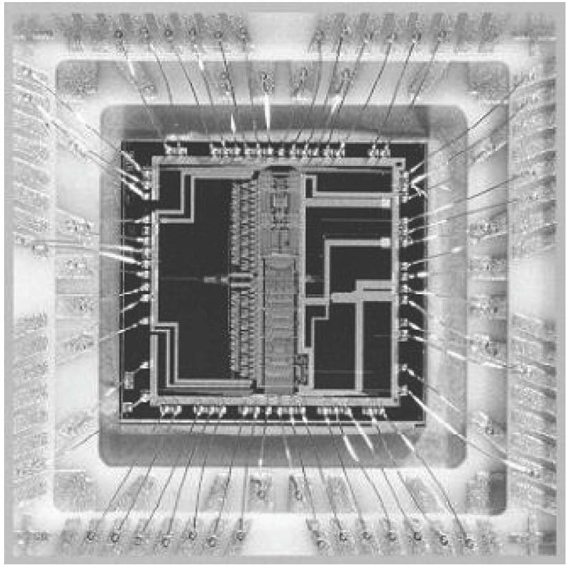
Crack Chip dsPIC30F6012 to break MCU dsPIC30F6012 security system, then copy embedded heximal from locked microcontroller dsPIC30F6012 flash and eeprom memory;
The core does not support a multi-stage instruction pipeline. However, a single stage instruction prefetch mechanism is used, which accesses and partially decodes instructions a cycle ahead of execution, in order to maximize available execution time when Crack Chip.
Most instructions execute in a single cycle with certain exceptions. The core features a vectored exception processing structure for traps and interrupts, with 62 independent which 4 are reserved) and 54 interrupts. Each interrupt is prioritized based on a user assigned priority between 1 and 7 (1 being the lowest priority and 7 being the highest), in conjunction with a predetermined ‘natural order’ if Crack Chip.
Traps have fixed priorities ranging from 8 to 15. vectors. The exceptions consist of up to 8 traps (of The programmer’s model is shown in Figure 2-1 and consists of 16 x 16-bit working registers (W0 through W15), 2 x 40-bit accumulators (ACCA and ACCB), STATUS register (SR), Data Table Page register (TBLPAG), Program Space Visibility Page register (PSVPAG), DO and REPEAT registers (DOSTART, DOEND, DCOUNT and RCOUNT) and Program Counter (PC) before Crack Chip.
The working registers can act as data, address or offset registers. All registers are memory mapped. W0 acts as the W register for file register addressing after Crack Chip.
· PUSH.S and POP.S
W0, W1, W2, W3, SR (DC, N, OV, Z and C bits only) are transferred.
· DO instruction
DOSTART, DOEND, DCOUNT shadows are pushed on loop start, and popped on loop end. When a byte operation is performed on a working register, only the Least Significant Byte (LSB) of the target register is affected. However, a benefit of memory mapped working registers is that both the Least and Most Significant Bytes can be manipulated through byte wide data memory space accesses when unlock mcu pic16f870 microchip.
Some of these registers have a shadow register associated with each of them, as shown in Figure 2-1. The shadow register is used as a temporary holding register and can transfer its contents to or from its host register upon the occurrence of an event. None of the shadow registers are accessible directly.
The following rules apply for transfer of registers into and out of shadows. The dsPIC® DSC devices contain a software stack. W15 is the dedicated software Stack Pointer (SP), and will be automatically modified by exception processing and subroutine calls and returns. However, W15 can be referenced by any instruction in the same manner as all other W registers before altera cpld epm7064stc44 jed code retieving.
This simplifies the reading, writing and manipulation of the Stack Pointer (e.g., creating stack frames). The dsPIC DSC core has a 16-bit STATUS register (SR), the LSB of which is referred to as the SR Low byte (SRL) and the Most Significant Byte (MSB) as the SR High byte (SRH). See Figure 2-1 for SR layout.
SRL contains all the MCU ALU operation status flags (including the Z bit), as well as the CPU Interrupt Priority Level status bits, IPL<2:0> and the Repeat Active status bit, RA. During exception processing, SRL is concatenated with the MSB of the PC to form a complete word value which is then stacked.
The upper byte of the STATUS register contains the DSP Adder/Subtracter status bits, the DO Loop Active bit (DA) and the Digit Carry (DC) status bit. The dsPIC DSC devices feature a 16/16-bit signed fractional divide operation, as well as 32/16-bit and 16/16-bit signed and unsigned integer divide operations, in the form of single instruction iterative divides.
Tags: feltöréssel védett mikrokontroller dsPIC30F6012 flash memória,repedésbiztos mikrokontroller dsPIC30F6012 flash memória,támadásbiztos mikrokontroller dsPIC30F6012 flash memória,törésbiztos mikrokontroller dsPIC30F6012 flash memória